

Fluid coating device,fluid coating method and plasma display panel
一种涂布装置、涂布方法的技术,应用在交流电等离子显示板、对表面涂布液体的装置、涂层等方向,能够解决变细、不能高品质形成连续线的始终端、涂布流量稳定性差等问题
- Summary
- Abstract
- Description
- Claims
- Application Information
AI Technical Summary
Problems solved by technology
Method used
Image

Examples
no. 1 Embodiment approach
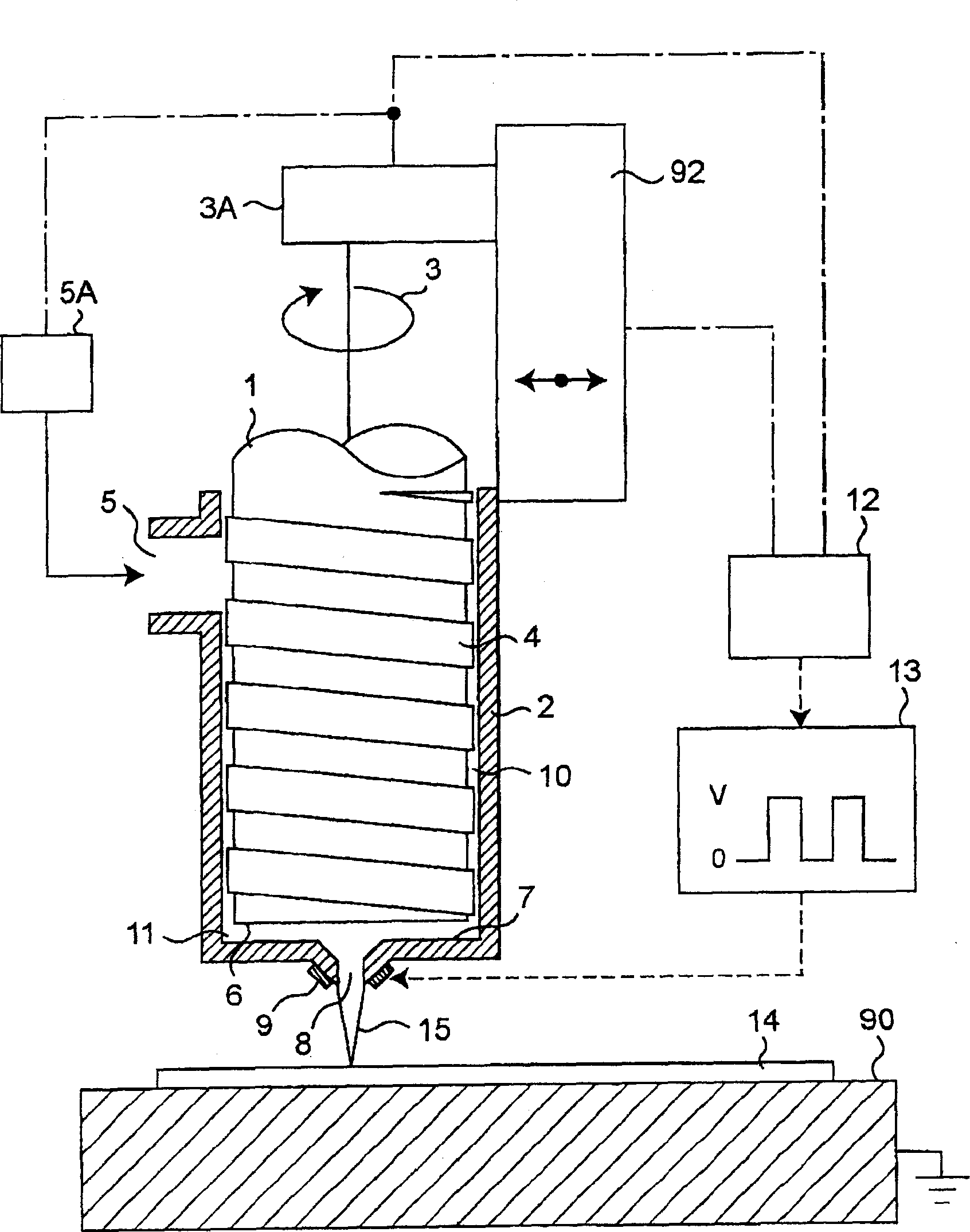
[0103] figure 1 It is a schematic partial cross-sectional view illustrating a fluid application device for carrying out the fluid application method according to the first embodiment of the present invention.
[0104] 1 is a piston, and 2 is a housing for accommodating the piston 1 . When using a non-conductive coating material, the shell 2 can use any insulating material or conductive material. When the shell 2 uses conductive material as a whole, the front end of the nozzle is closest to the substrate, so the electric field intensity is the largest, which will not affect The function of electric field control. However, when a high voltage is not applied to the entire casing 2 in consideration of safety, if Figure 29 As shown in the specific example, it is also possible to only provide the discharge part of the electrode (in Figure 29 364) uses insulating materials, and other positions use conductive materials. In addition, a conductive material or an insulating materi...
no. 2 Embodiment approach
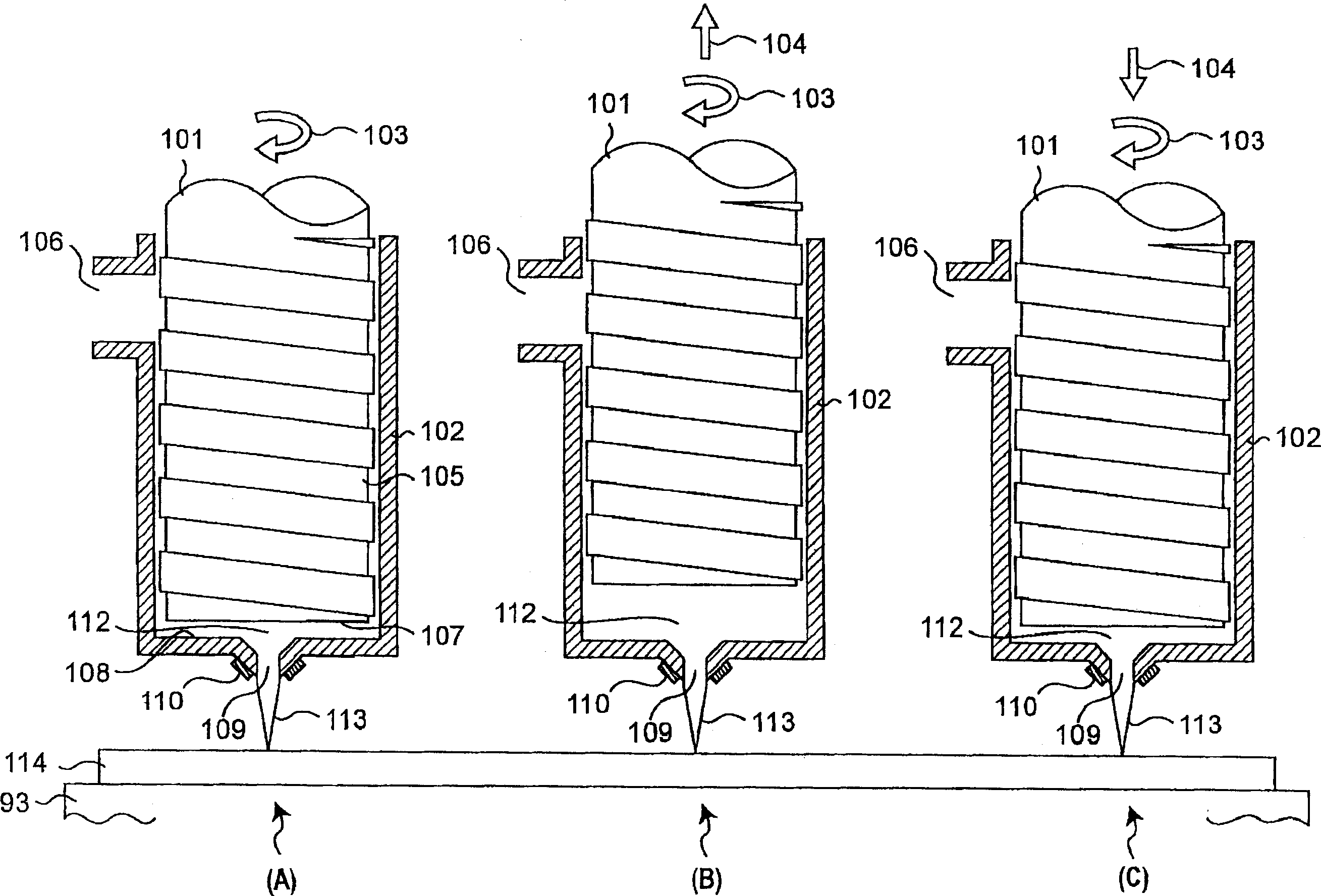
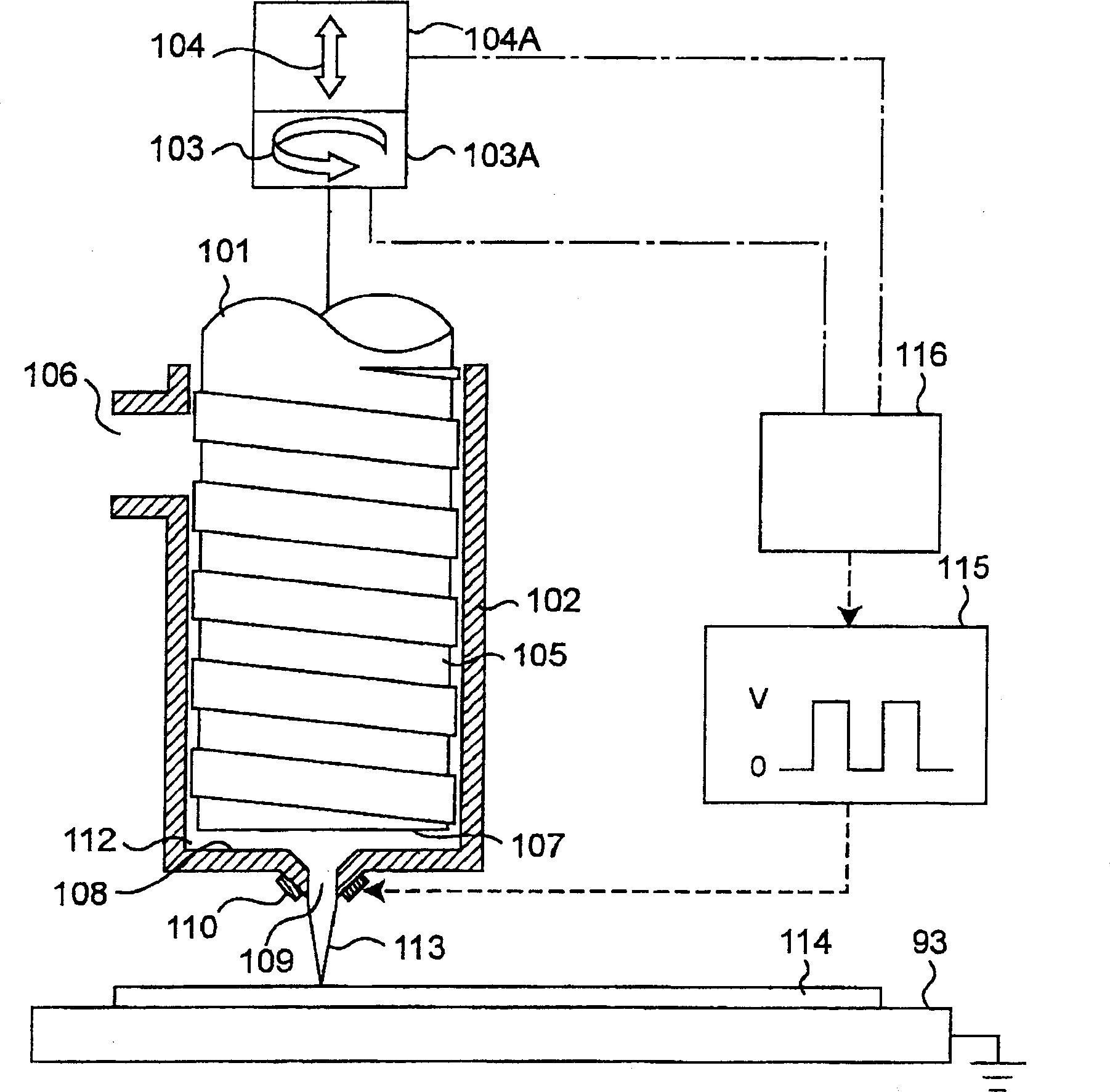
[0117] figure 2 , Figure 3A and Figure 3B It is a schematic partial cross-sectional view illustrating a fluid application device for implementing a fluid application method according to a second embodiment of the present invention, figure 2 (A), (B), and (C) each show a flow chart from the state of continuous coating to the state of shutoff coating and then to the state of starting coating. The piston shaft of the dispenser used in the fluid application device and method of the second embodiment, such as Figure 10 As shown in the specific example of , it is a structure that can be rotated and linearly moved by a 2-degree-of-freedom driver.
[0118] 101 is a piston, and 102 is a housing for accommodating the piston 101 . The piston 101 is housed in a housing 102 as a fixed side so as to be able to rotate independently and move linearly. When using a non-conductive coating material, the housing 102 can use any insulating material or conductive material. When the whole ...
no. 3 Embodiment approach
[0129] Figure 4A and Figure 4B It is a schematic partial cross-sectional view illustrating a fluid application device capable of implementing the fluid application method according to the third embodiment of the present invention, as the suction force generated to return to the inside of the discharge nozzle: f 2 Another example of the device, showing the use of thrust dynamic pressure seals. The piston shaft of the dispenser used in the fluid application device and method of the third embodiment is the same as the fluid application device and method of the second embodiment, and is driven by a 2-degree-of-freedom driver (specifically, a rotation transmission device) 603A and axial movement device 604A) can simultaneously rotate and linearly move the structure. A thrust dynamic pressure seal is formed between the discharge-side end surface of the piston shaft and its opposing surface.
[0130] 601 is a piston having the same thread groove as that of the piston 101 , and 6...
PUM
 Abstract
Description
Claims
Application Information