
Inductive building separated solar water heater and operating controlling method

A solar water heater and building-type technology, applied in solar thermal power generation, solar thermal installations, sustainable buildings, etc., can solve the problems of affecting the architectural shape, inability to meet, inconvenient use, etc., to achieve improved thermal energy utilization, reasonable structural design, Easy to use and reliable results

Inactive Publication Date: 2004-12-08
XINJIANG GAISHIHAICHUAN ENVIRONMENT PROTECTION TECH CO LTD
View PDF0 Cites 2 Cited by
  • Summary
  • Abstract
  • Description
  • Claims
  • Application Information

AI Technical Summary

Problems solved by technology

Therefore, in actual use, it has the following disadvantages: 1. The structural design is not reasonable enough. The heat collecting tube and the water storage tank are connected together and cannot be installed separately, so that the water stored in the vacuum tube cannot be taken, and the heat energy utilization rate is low, generally only about 60%. The highest can only reach about 80%. At the same time, the water heater and the building cannot be matched harmoniously. It is a free exchange, so the utilization rate of heat energy is low and the degree of automation is low. At the same time, because the water storage tank is on the roof, it is difficult to clean the system after fouling, which brings inconvenience to use and has potential safety hazards; 3. The scope of application is narrow, due to The thermal efficiency of the existing products is low, and the thermal energy storage is the highest point, so it cannot meet the requirements of using energy-saving products in large public places, government schools, multi-storey and high-rise buildings; Garden-style cottages are also prohibited from installing such solar water heaters

Method used


Image

  • Inductive building separated solar water heater and operating controlling method
  • Inductive building separated solar water heater and operating controlling method
  • Inductive building separated solar water heater and operating controlling method

Examples


Embodiment 1

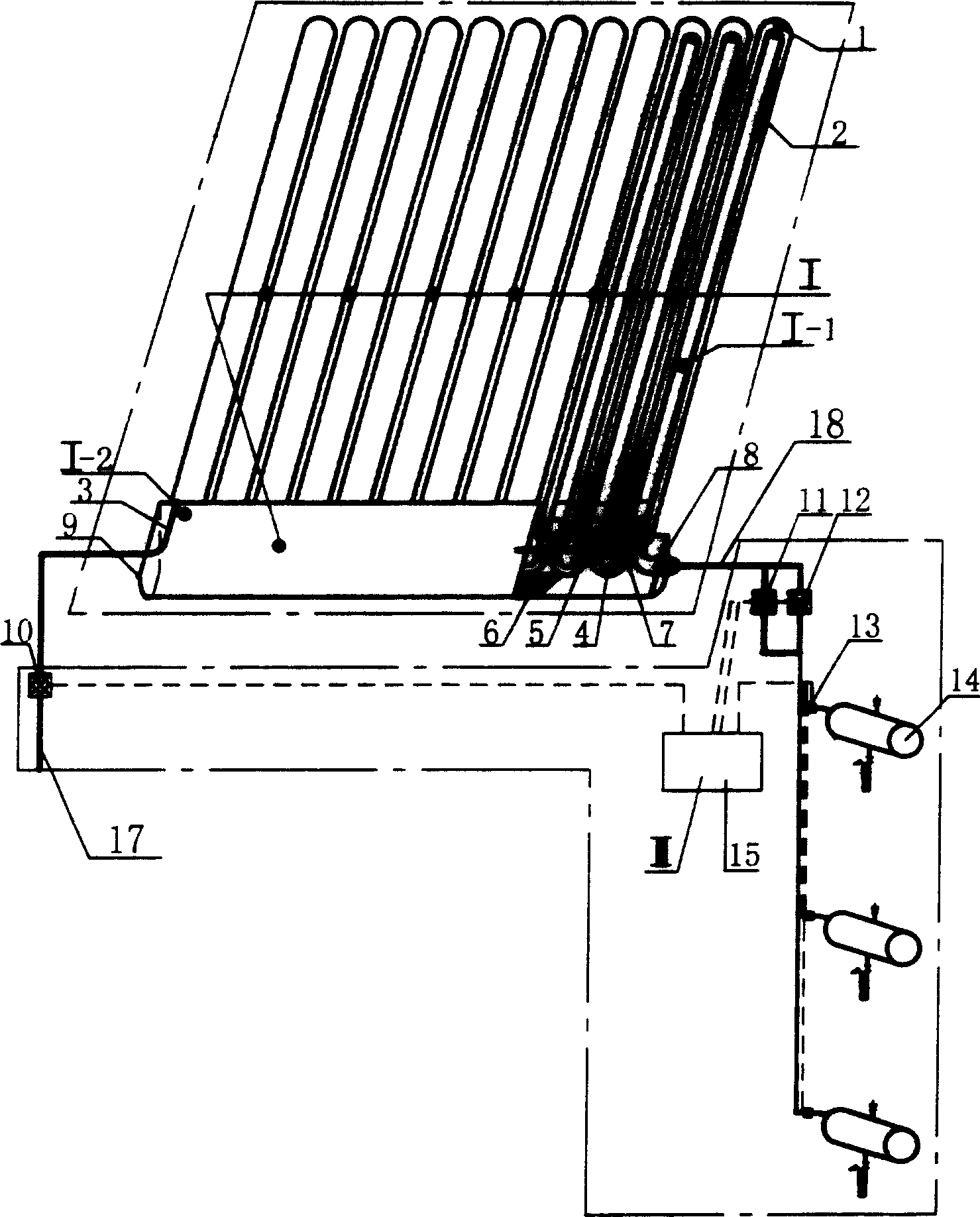
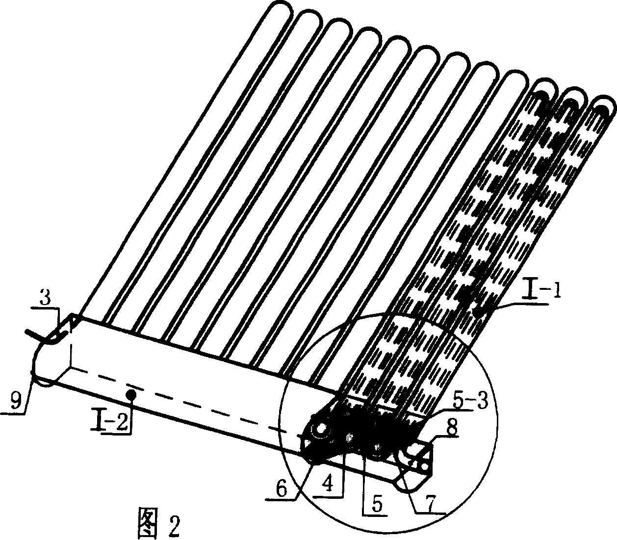
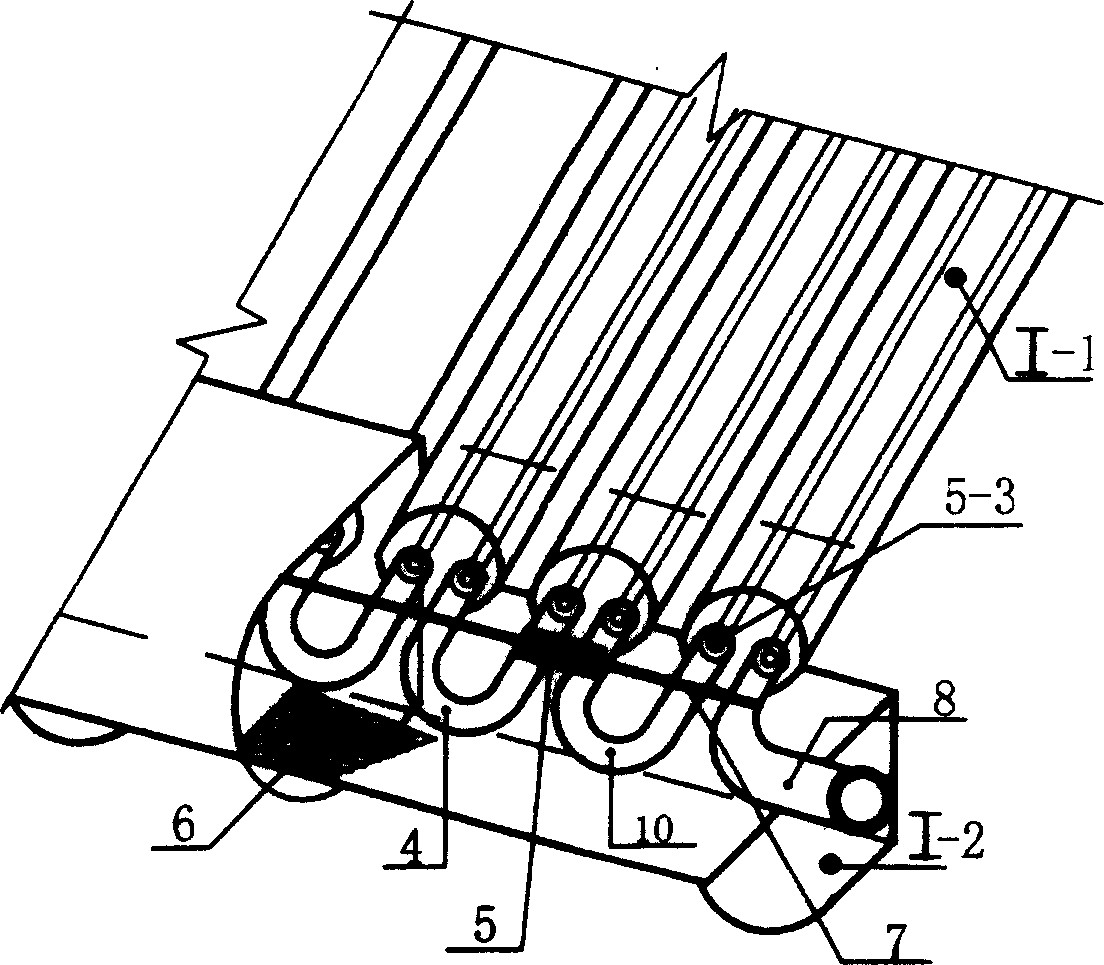
[0026] see figure 1 - Fig. 5, the present invention mainly is made up of heat collecting tube device I, water storage tank 14 and control part III, and heat collecting tube device I comprises heat collecting tube part I-1 and induction tube part I-2, and heat collecting tube part I-1 is made of glass tube 1 and heat collecting tube 2, the shape of heat collecting tube 2 is U-shaped; induction tube part I-2 includes induction tube 4, outer cover 9 with insulation layer 6, connector 7, induction inlet and outlet pipes 3, 8, induction tube 4 It is a U-shaped tube, which is plugged with the heat collecting pipe 2, and the induction pipe 4 is also bonded with the connecting body 7, and the connecting body 7 is bonded with a thermal sensor 5, and the induced water inlet and outlet pipes 3, 8 are also connected with the heat collecting pipe 2. Docking. The control part III includes a computer control device 15, an inlet water flow regulating valve 10, an outlet water temperature con...

Embodiment 2

[0032] see Figure 7-8 , which is a structural schematic diagram of the application of the present invention in engineering. Said engineering refers to the installation area of ​​more than 100 square meters, and when the required water consumption is greater than 1 liter / second, the diameter of the induction tube requires a solar thermal energy of greater than 25 mm. Water system, wherein, the induction pipe in the induction pipe part I-2 is a continuous induction pipe 16, and the rest are the same as the system example 1.

[0033] See Figure 5, Figure 9 , the present invention makes the cold medium water enter the heat collecting tube device 1 by way of induction, and heat energy exchange is performed in the heat collecting tube device 1, while hot water then flows out from the water outlet 8. That is: first, the whole is in a closed state, and when the roof heat collecting tube device 1 absorbs heat, the temperature rises, and the signal is sent to the indoor computer cont...


PUM


Abstract

In the present invention, heat collection tube and water storage tank are designed in separation type as they two are connected by connection pipe, heat collection tube is set at external of building and water storage tank is set in room of the user, induced mode is used to carry on forced heat exchange for heat collection tube and connection pipe in order to raise heat efficiency.

Description

technical field [0001] The invention relates to a solar water heater and its operation control method, in particular to an inductive building-type split solar water heater and its operation control method. Background technique [0002] The solar water heater in the prior art is composed of a water storage tank, a bracket and a glass vacuum heat collecting tube, connected to the inlet and outlet pipes to achieve the purpose of heat collection, heat exchange and hot water. Before use, cold water must be supplied to the commanding heights In the water storage tank, the water flows into the glass vacuum tube or the eloquence, and the heat pipe type glass vacuum tube and the heat conduction head are inserted into the water storage tank to heat the water; when in use, drain the cold water in the tube, take hot water or add a circulation pump to circulate and then use hot water . Therefore, in actual use, it has the following disadvantages: 1. The structural design is not reasonab...

Claims


Application Information

Patent Timeline
Patent Type & Authority Applications(China)
IPC IPC(8): F24J2/04
CPCY02E10/44Y02B10/20
Inventor 王金炬
Owner XINJIANG GAISHIHAICHUAN ENVIRONMENT PROTECTION TECH CO LTD
Learn More