Differential comparing circuit system

A comparison circuit and differential technology, applied in logic circuits, logic circuits with logic functions, electrical components, etc., can solve problems such as increased power loss, large current, and waste of power

Inactive Publication Date: 2004-12-08
WINBOND ELECTRONICS CORP
View PDF0 Cites 5 Cited by
  • Summary
  • Abstract
  • Description
  • Claims
  • Application Information

AI Technical Summary

Problems solved by technology

[0007] Although figure 2 The circuit can expand the received input voltage range, but the tail-current transistors (tail-current transistor) 20, 21 are always on, and will not dynamically change with the corresponding PMOS or NMOS switch state , so no matter whether PMOS or NMOS is receiving the transmission signal, there will be a tail-current transistor (tail-current transistor) in the conduction state, but it does not operate, thereby increasing the loss of the power supply
[0008] Moreover, when the input voltage belongs to the intermediate voltage, the PMOS and NMOS will be turned on at the same time, causing the output tail current to be too large, thus wasting power

Method used


Image

  • Differential comparing circuit system
  • Differential comparing circuit system
  • Differential comparing circuit system

Examples


Embodiment Construction

[0027] The differential comparator circuit system of the present invention can be fully understood from the description of the following embodiments, so that those skilled in the art can complete it accordingly. However, the implementation of the present invention cannot be limited by the following embodiments. state.

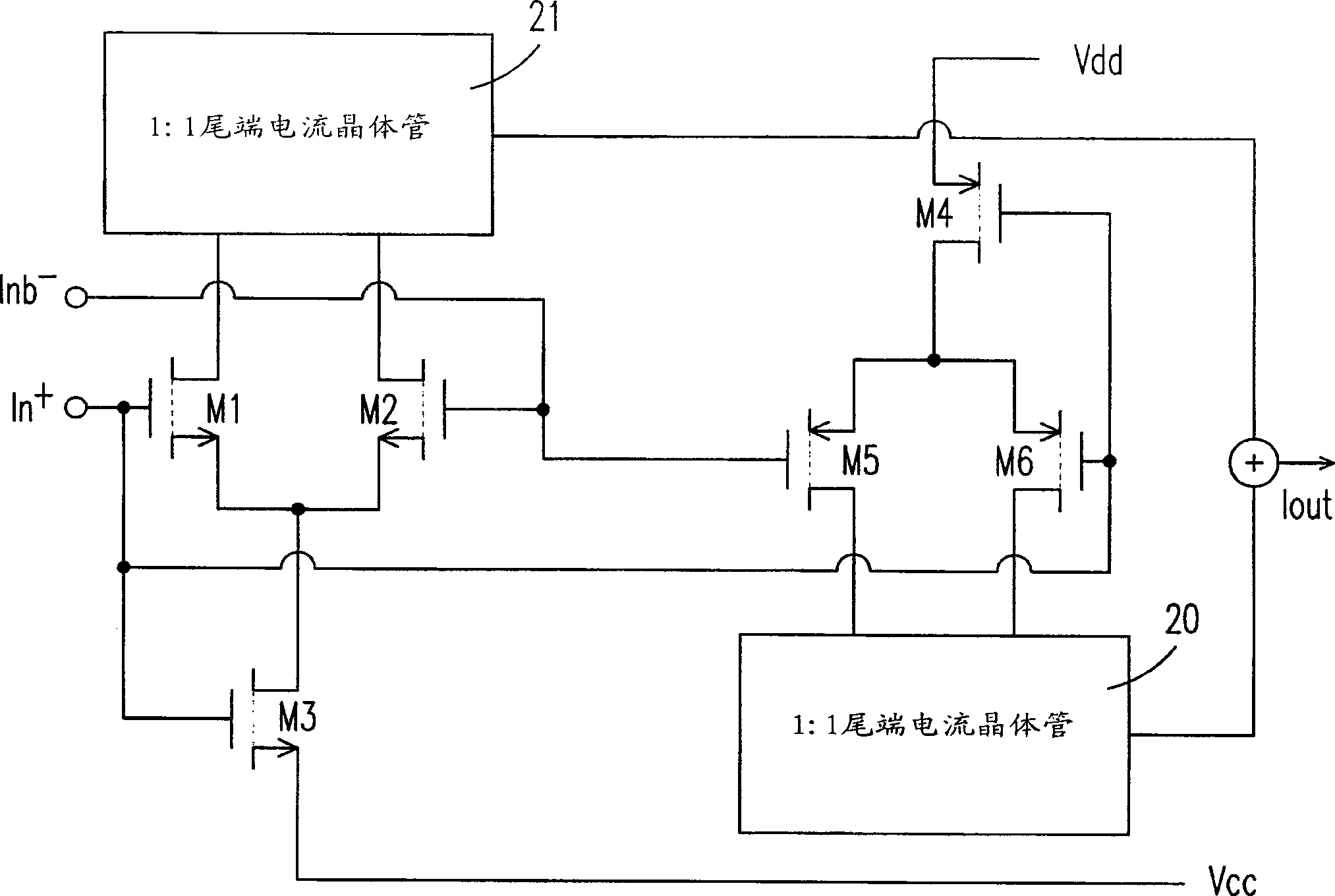
[0028] see image 3 And FIG. 4, which is a circuit block diagram and a detailed circuit structure diagram of a preferred embodiment of the present invention.

[0029] The differential receiving and comparing circuit system of the present invention can be applied to the transmission end of the Universal Serial Bus (USB) interface, and is used to receive all input signals in the voltage range of 0 ~ Vdd (about 0 ~ 3.3 volts), and output them after amplifying An output voltage, wherein the voltage range can be subdivided into a first part of a higher voltage (about 2-3.3 volts) and a second part of a lower voltage (about 0-2 volts), the system may include: a The...


PUM


Abstract

This invention is a deference comparison circuit system. It is used to receive all input signals within a certain voltage range, then amplify and output them. Especially the voltage range is a part of higher voltage and a part of lower voltage. The system comprises: a first deference comparator used to receive the first part input signals within the voltage range and amplify them for outputting them; a checking circuit making electrical connection with the first deference comparison circuit generates a trigger signal, as detecting the first deference comparison circuit can't work because the voltage of input signal is below the first part of the voltage range; a second deference comparator used to connects to the checking circuit corresponds the driving of the trigger signal to receive the input signals of the second part within the voltage range and amplify them for generating the output voltage.

Description

(1) Technical field [0001] The invention relates to a comparison circuit system, in particular to a differential comparison circuit system suitable for a universal serial bus (Universal Serial Bus, USB) interface transmission terminal. (2) Background technology [0002] Universal Serial Bus (USB) is a peripheral device interface, which is jointly developed by seven hardware and software manufacturers. The transmission rate of this interface has two forms: 1.5Mbps and 12Mbps. To 127 peripheral devices. [0003] Since the universal serial bus interface (USB) has very strict regulations on the range of the voltage value Vin that can receive input signals, it must be satisfied that all input voltages within a specific range (0.8-2.2V) can be received. [0004] Please refer to Figure 1(a) and (b), which are traditional circuits used to receive input signals, where Figure 1(a) uses N-type metal oxide semiconductor transistors (NMOS) to receive input voltage values, which can only...

Claims


Application Information

Patent Timeline
Patent Type & Authority Applications(China)
IPC IPC(8): H03K19/00H03K19/20
Inventor 印瑞德王锡源
Owner WINBOND ELECTRONICS CORP
Why Eureka
Try Eureka