Rotation sensor
A rotary detector technology, applied in the direction of converting sensor output, instruments, measuring devices, etc., can solve the problems of reducing reliability, increasing cost, difficult to determine the rotary detector, etc., and achieve the effect of eliminating pulsation components
- Summary
- Abstract
- Description
- Claims
- Application Information
AI Technical Summary
Problems solved by technology
Method used
Image
Examples
Embodiment 1
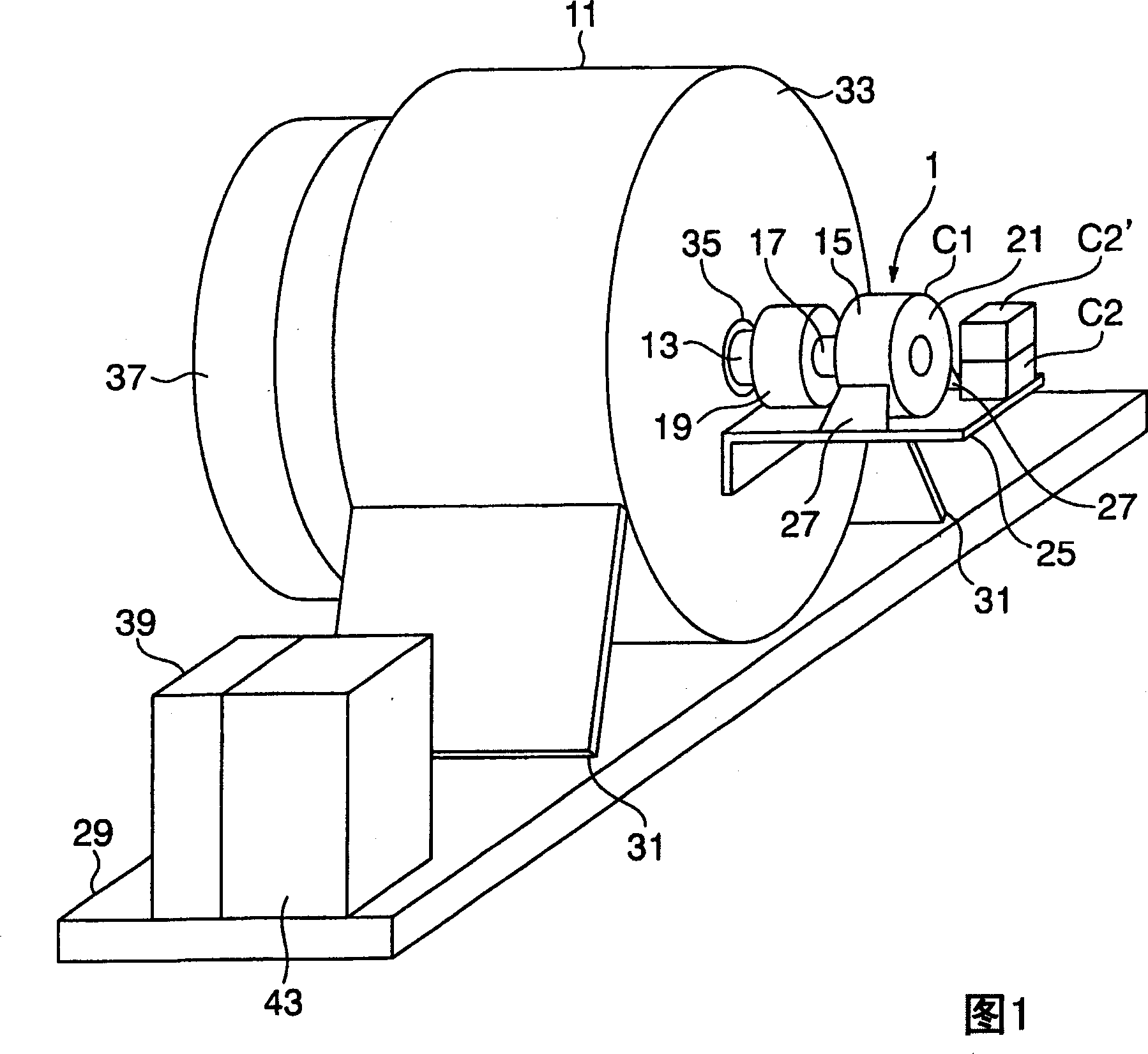
[0067] A first embodiment of the present invention will be described in detail with reference to FIGS. 1 to 7 .
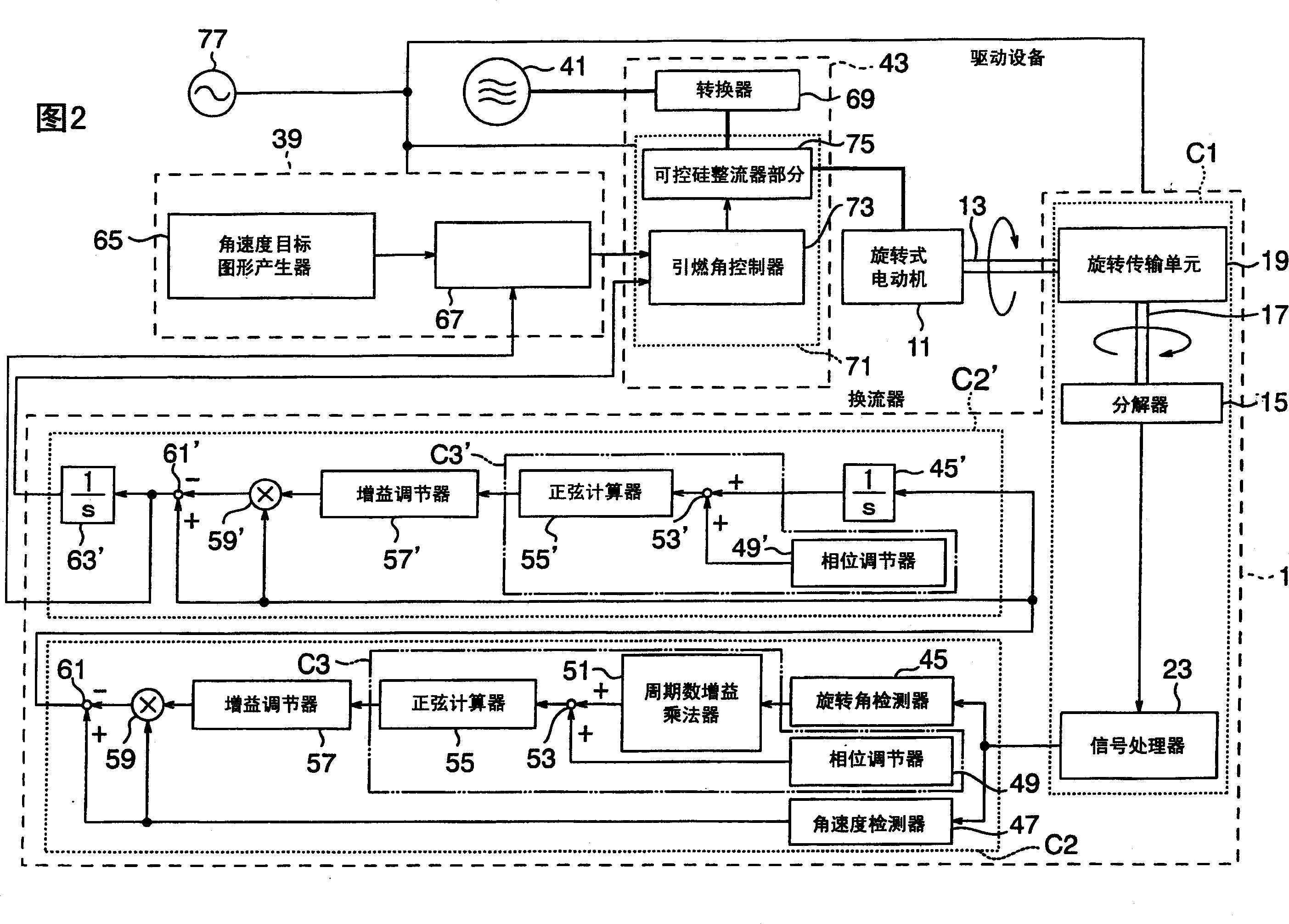
[0068] In FIGS. 1 and 2, reference numeral 1 denotes the entire rotary detector in the first embodiment. The rotary detector 1 includes a rotary detector unit C1 and rotary calculator units C2 and C2'.
[0069] The rotary detector unit C1 of this embodiment is connected to the detected device here which includes the rotor rotating shaft 13 of the rotary motor 11, and the rotary detector unit C1 includes a resolver 15, a rotary input shaft 17, and a rotation transmission unit 19. The resolver 15 outputs a voltage proportional to the rotation angle of the rotor rotation shaft 13 . The rotary input shaft 17 is directly connected to the rotor of a resolver 15, not shown. The rotation transmission unit 19 is connected to the rotor rotation shaft 13 and transmits the rotation of the rotor rotation shaft 13 to the rotation input shaft 17 of the resolver 15 .
[0070] ...
Embodiment 2
[0084] Subsequently, a second embodiment of the present invention will be described with reference to FIGS. 8 and 9 .
[0085] In a first embodiment, the output signal of the rotary detector unit C1 is processed by a series of rotary computing units C2 and C2'. However, this does not limit the number and structure of the rotary calculation units, which can be modified according to the characteristics of the ripple component in the signal output by the rotary detector. For example, in the rotary detector unit C1 which includes the rotary encoder 87 instead of j15, there is no possibility of the second pulsation component caused by this j15. On the other hand, the adjustment phase fluctuates according to the torque direction of the rotary electric motor 11 when there is backlash in the rotary transmission unit 19 which includes a coupling. When the load of the rotary motor 11 is loaded to apply an external force to the rotor rotating shaft 13 in the direction in which the shaft...
Embodiment 3
[0088] Refer to Figure 10 and Figure 11 A third embodiment of the present invention will be described.
[0089] In the first and second embodiments, the rotary detection units (C1 and C1') are adjacent to the rotary calculation units (C2, C2', and C2") and together constitute the entire rotary detector 1, But this is not to limit the distance and the position of the rotary detection unit and the rotary calculation unit. As shown in Figures 10 and 11, the rotary calculator unit C2 can be incorporated into the speed control device 39 and the drive device 43. Because the drive device 43' needs the rotation angle information, so the output of the rotary calculator unit C2 is input to the ignition angle controller 73 through the integrator 63'. The rotary calculator unit C2' is not used here because it can be ignored by the rotary transmission unit The resulting first pulsation component. In this embodiment, the rotary detector unit C1 can be installed in the rotary motor 11, whi...
PUM
 Abstract
Description
Claims
Application Information
 - R&D
- Intellectual Property
- Life Sciences
- Materials
- Tech Scout
- Unparalleled Data Quality
- Higher Quality Content
- 60% Fewer Hallucinations
Browse by: Latest US Patents, China's latest patents, Technical Efficacy Thesaurus, Application Domain, Technology Topic, Popular Technical Reports.
© 2025 PatSnap. All rights reserved.Legal|Privacy policy|Modern Slavery Act Transparency Statement|Sitemap|About US| Contact US: help@patsnap.com


