Cutting blade for machining screw thread

A technology for threading and inserting, applied in the field of indexable threading inserts, can solve the problems of easily damaged tools and inserts, can not be used as CNC machining, damage the machined surface, etc. Effect

Active Publication Date: 2004-12-29
ZHUZHOU HARD ALLOY GRP CO LTD
View PDF0 Cites 22 Cited by
  • Summary
  • Abstract
  • Description
  • Claims
  • Application Information

AI Technical Summary

Problems solved by technology

Generally, thread cutting inserts are provided with some grooves on the rake face of the cutting edge as chip breakers, but in actual use, we found that the curvature of chips formed by cutting of such inserts is too large, and the flow of chips changes by changing the cutting edge. The parameters cannot be well controlled, and it is easy to damage the tool and blade, or even damage the processed surface, especially when processing stainless steel, alloy materials, non-ferrous metals and other materials with good plasticity and viscosity, this phenomenon is more serious; It is also easy to cause danger to the operator
At the same time, thread processing can only be used as a separate process, not as a part of CNC machining, and the production efficiency is not high.

Method used


Image

  • Cutting blade for machining screw thread
  • Cutting blade for machining screw thread
  • Cutting blade for machining screw thread

Examples


Embodiment Construction

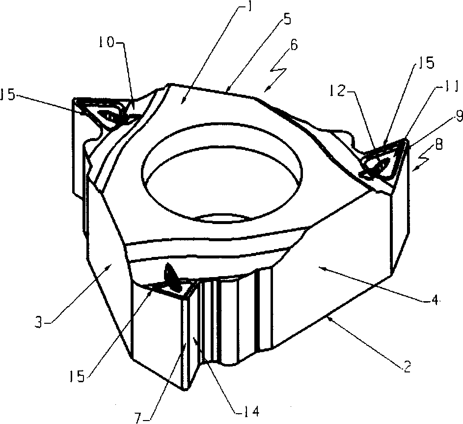
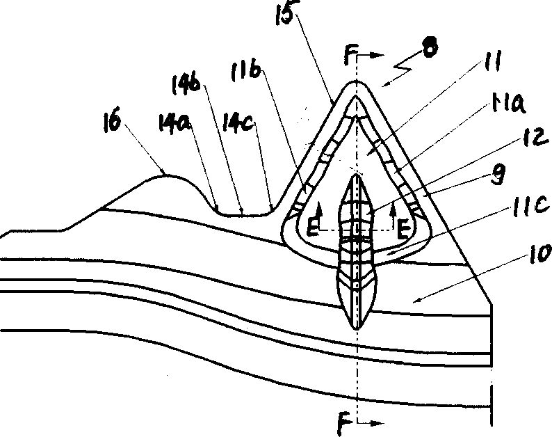
[0020] Such as Figure 1 to Figure 4 As shown, the indexable threading insert of the present invention comprises an insert body 6 and a cutting edge angle 8 composed of an upper surface 1, a lower surface 2 and three groups of side surfaces 3, 4, 5 connecting the above two surfaces; The side faces of the group are connected by arc surfaces 7 and form a cutting edge angle 8; the top surface of each cutting edge angle is a blade rake face 9 formed by a plane with the same angle with the upper and lower surfaces 1 and 2, and Three sets of side faces 3, 4, 5 intersect to form three cutting edges 15 respectively, and a wiper edge 14 is designed on one side of each cutting edge 15; the rake face 9 is connected with the blade body 6 through an arc surface 10; A fan-like groove 11 is designed in the rake face 9, and its angle bisector is located on the angle bisector of the cutting edge angle 8. The two side walls 11a, 11b of the groove 11 are wavy curved surfaces; the blade is also d...


PUM


Abstract

The thread machining cutter with unique groove form includes upper surface, lower surface and three side surfaces constituting cutter body and cutting bit angle. Any two side surfaces are connected by arced surface to constitute cutting bit angle, the top is the front edge surface connected to the cutter body via an arced surface, the front cutter surface and the side surface form cutting edge, and each of the cutting edge is provided with one trimming edge. The front cutting surface has one fanned notch with wavy side walls and one boss with front end extending to inside the notch and tail end extending backwards and ending in the arced surface. The present invention can control the cutting scrap direction and shape during machining, raise the smoothness of the machined surface and the machining efficiency, and may be used in triangular, rectangular, trapeziform and other shaped thread.

Description

technical field [0001] The invention relates to a thread processing insert, especially an indexable thread processing insert. Background technique [0002] The thread processing is special, it is different from the ordinary outer circle turning, the two edges of the thread cutter participate in the cutting at the same time and the feed rate is large, the chip becomes wider and wider with the increase of the cutting depth, and the wide and hard chip is very Difficult to break, easy to wrap around workpieces, tools, and fixtures. In addition, the thread cutter has a small tip angle and low strength. Chips rotating at high speed with the workpiece can easily hit the blade and cause chipping. To solve the above problems, it is necessary to solve the problem of chip flow and chip breaking. Generally, thread cutting inserts are provided with some grooves on the rake face of the cutting edge as chip breakers, but in actual use, we found that the curvature of chips formed by cuttin...

Claims


Application Information

Patent Timeline
Patent Type & Authority Applications(China)
IPC IPC(8): B23G5/00B23G5/18
Inventor 李明张京王社权汤爱民
Owner ZHUZHOU HARD ALLOY GRP CO LTD
Why Eureka
Try Eureka