
Automatization system for marshalling station pispatching train

An automation system and technology for shunting locomotives, applied in the field of shunting locomotive automation systems, can solve the problems that information cannot be shared, cannot be used in marshalling yards, complex and other problems

Active Publication Date: 2005-01-05
CRSC RESEARCH & DESIGN INSTITUTE GROUP CO LTD
View PDF4 Cites 8 Cited by
  • Summary
  • Abstract
  • Description
  • Claims
  • Application Information

AI Technical Summary

Problems solved by technology

Since neither the locomotive itself nor the ground can confirm the location of the locomotive, this type of system still needs a large number of sensor devices on the ground for locomotive identification, to identify the location of the locomotive and check the relationship with the route, in order to distinguish the received locomotive from the locomotive. The corresponding information part is relatively complex and limited by the region, and cannot be applied to the entire marshalling station
[0005] In addition, there is no integrated automation system for marshalling stations in the complete sense at home and abroad.
There are some railway marshalling station automation systems that implement automatic control of certain operating systems of the marshalling station in the prior art. At present, there are also some management systems responsible for vehicle dispatching such as slip operation planning systems and information processing systems. In addition, In the prior art, there are also some related train and vehicle detection devices working in the marshalling yard, but so far, in the technical field, the above-mentioned process control system, vehicle detection system and dispatch management system have not been integrated into the same comprehensive system. As a result, the planning information of trains, shunting trains, locomotives, and vehicles and the execution information of route control are not on the same working platform, and the information cannot be shared within the entire marshalling yard

Method used


Image

  • Automatization system for marshalling station pispatching train

Examples


Embodiment Construction

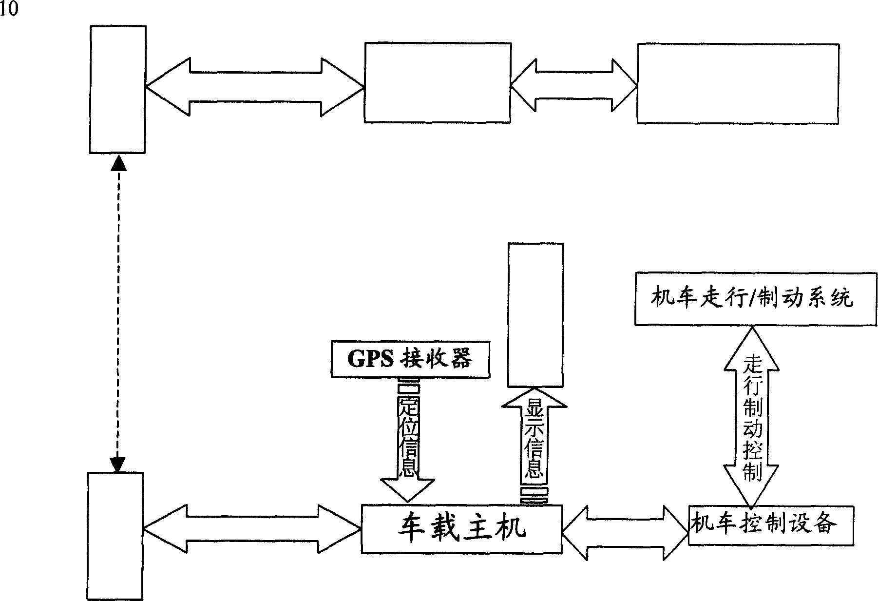
[0023] figure 1 The functional block diagram in shows the marshalling station dispatching automation system according to the preferred embodiment of the present invention. As can be seen from the figure, the system includes three parts: ground equipment, communication equipment, and vehicle equipment. The ground equipment is responsible for collecting, collating and organizing various shunting information on the shared information database platform of the marshalling yard management system, which includes shunting and shunting plan information, yard indication information, shunting tracking information, and required locomotive speed Information, vehicle status information, and GPS positioning information. The communication equipment adopts Gigabit Ethernet and wireless local area network seamlessly connected data transmission channel, and high-speed bidirectional real-time transmission of required control and display information between the ground and all dispatchers in the m...


PUM


Abstract

An automation system for the classfying locamotive in classification yard is a component of the integrated automation system for classification yard for realizing the computer aided schedule. It integrates the signaling function and remote control function of original hump-type classification yard.

Description

technical field [0001] The invention relates to an automation system for shunting locomotives (short for shunting locomotives) in railway marshalling yards, which belongs to the technical field of realizing informatization and automation in railway marshalling yards. Background technique [0002] The shunting locomotive is used as the driving force for the shunting operation in the railway marshalling yard, and usually only moves within the marshalling yard range. The scheduling plan of the swapping machine includes the matching of the tuning machine and the shunting plan, the timing of machine tuning and maintenance, the dining time arrangement of the drivers and passengers, the selection of the locomotive travel path, the scheduling optimization strategy and balance when multiple locomotives are in operation, etc. At present, The scheduling plan of the shunting locomotives in the marshalling station is manually carried out by the staff on paper, and the scheduling informat...

Claims


Application Information

Patent Timeline
IPC IPC(8): B61L27/04
Inventor 丁昆周暐
Owner CRSC RESEARCH & DESIGN INSTITUTE GROUP CO LTD
Learn More