Porous restrictor for gas bearing

A fluid bearing and porous body technology, which is applied in the field of current limiting devices, can solve problems such as high cost and blockage of small particles, and achieve the effects of reducing labor costs and improving reliability.

Inactive Publication Date: 2005-01-05
GLOBAL COOLING
View PDF3 Cites 14 Cited by
  • Summary
  • Abstract
  • Description
  • Claims
  • Application Information

AI Technical Summary

Problems solved by technology

All these existing technologies and structures have the disadvantages of high cost or being easily clogged by small particles in the working gas

Method used


Image

  • Porous restrictor for gas bearing
  • Porous restrictor for gas bearing
  • Porous restrictor for gas bearing

Examples


Embodiment Construction

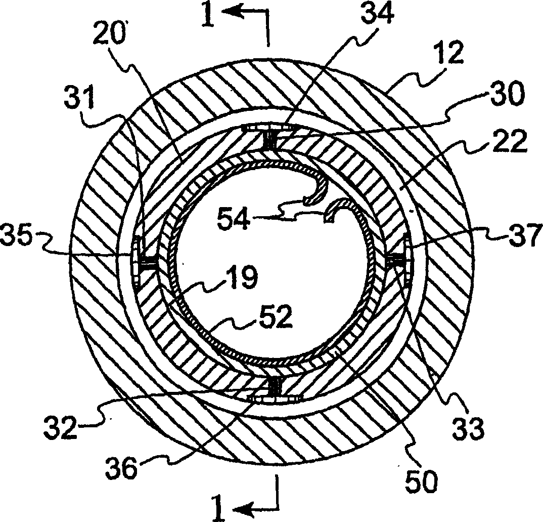
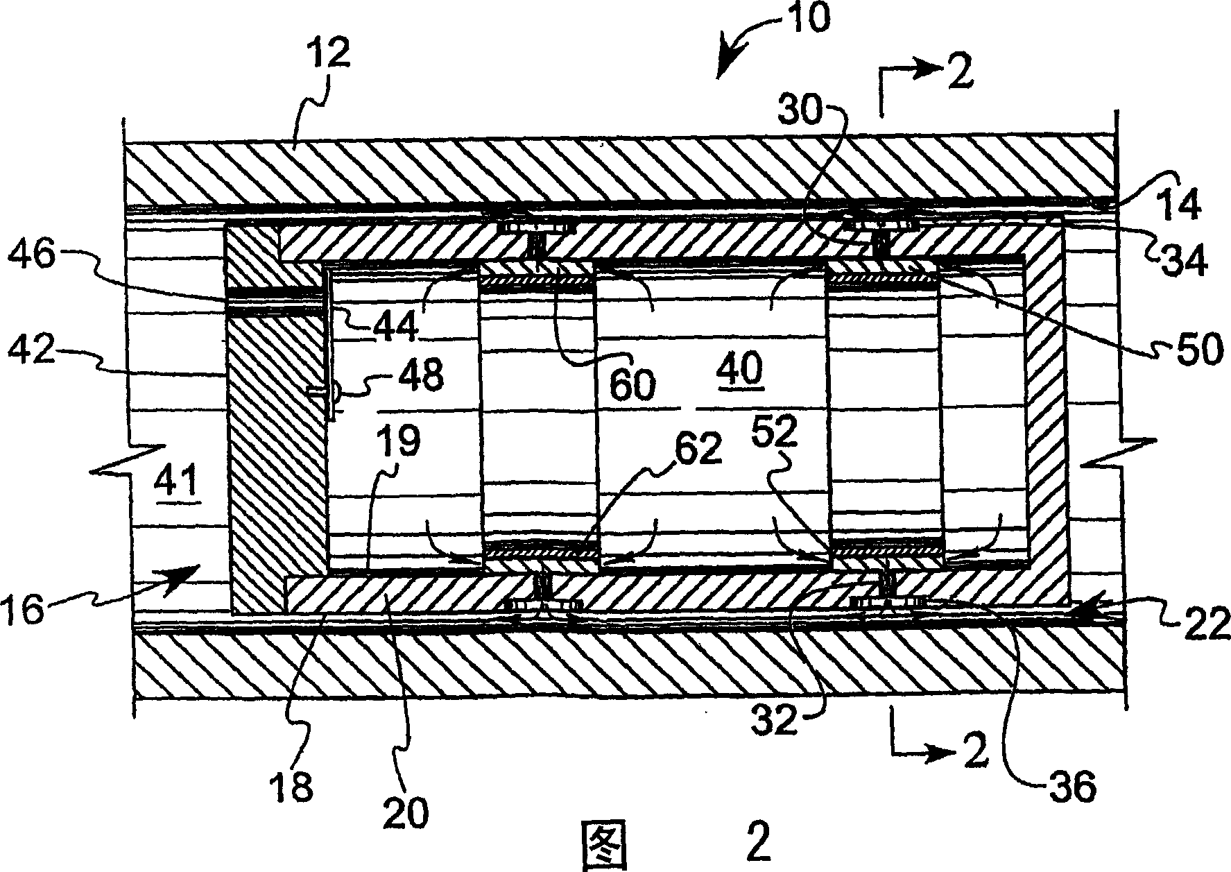
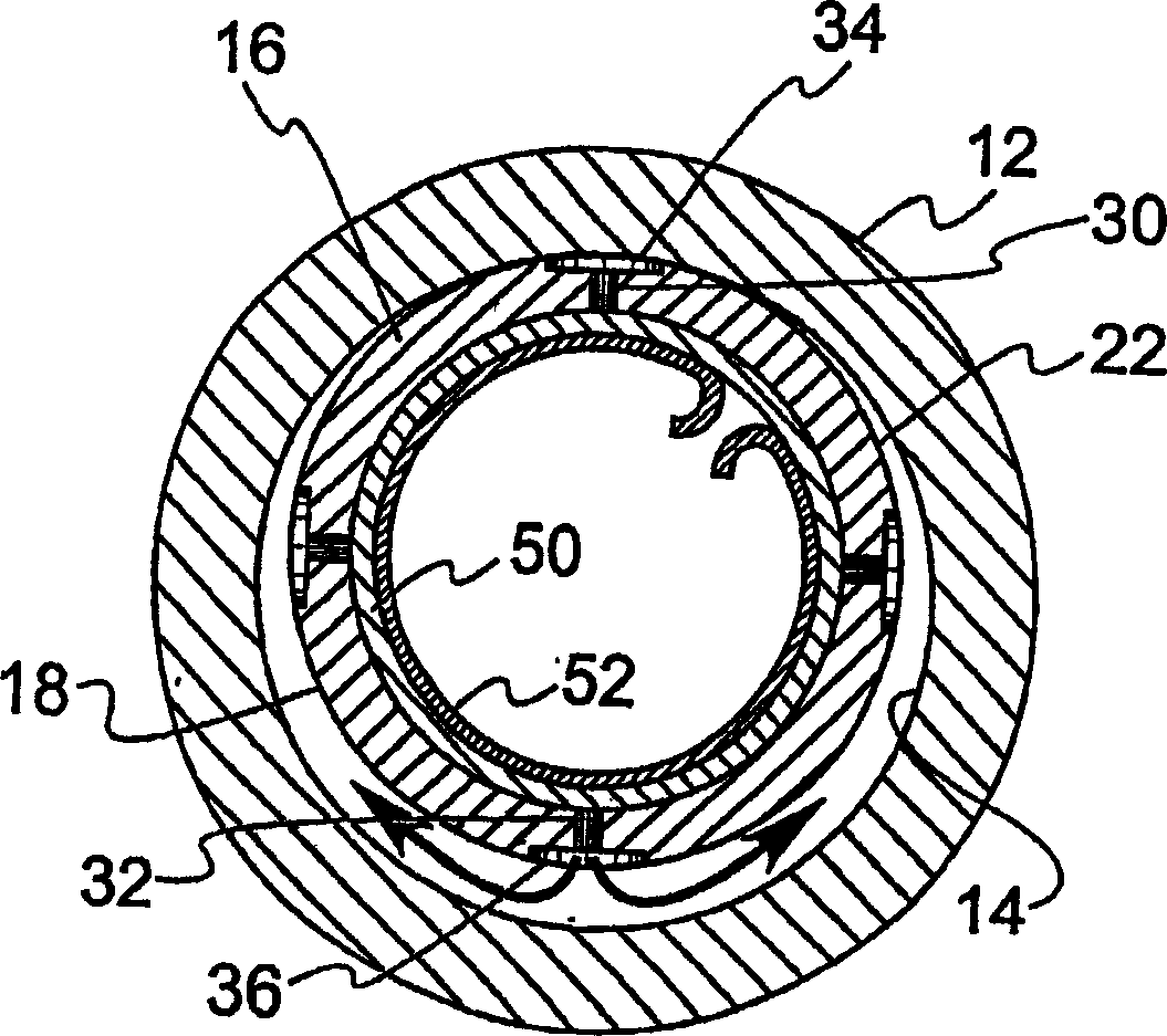
[0021] figure 1 Shown is a preferred embodiment of the invention wherein a free piston Stirling cycle device 10 includes a cylindrical housing 12 with an inner side wall surface 14 . Figure 4 The piston 16 shown has an outer cylindrical surface 18 on the side wall 20 which abuts the inner cylindrical surface 14 of the housing side wall 12 .

[0022] An annular gap 22 is formed between the piston 16 and the housing 12 into which a working fluid such as helium flows. The dimensions of the annulus have been exaggerated in the figures. In the contemplated embodiment, the diameter difference between the outer surface of the piston 16 and the inner surface 14 of the housing is about 15 to 35 microns. Therefore, when the piston 16 is at radial dead center (zero eccentricity), the annular gap is half of this difference in diameter, ie equal to 7.5 to 17.5 microns. Gas flows through the annulus 22, resulting in what is commonly known as a hydrodynamic bearing.

[0023] The gas ent...


PUM


Abstract

A gas restrictor particularly useful for application in gas bearings as used, for example, in free-piston Stirling cycle machinery. Porous strip material (52) together with a backing plate (60) and orifice (32) is used to provide the restriction to the flow of gas into an annular gap (22) between a piston (16) and a cylinder (12).

Description

technical field [0001] The present invention relates generally to gas bearings (also known as gas bearings) used in machines such as free piston Stirling machines, and more particularly to flow limiting devices for use with gas bearings. Background of the invention [0002] In many different mechanical devices, pistons reciprocate within cylinders in housings. Due to precision machining, a small annular gap can be formed between the cylinder wall and the piston wall. For example, in a Stirling cycle machine, the housing encloses a working volume connected to one end of the piston and a rear volume connected to the other end of the piston. The term "piston" generally refers to any piston-like object, including displacers in Stirling cycle machinery. A working gas, such as helium, fills the working space, rear space, and other areas within the housing. [0003] Because the piston walls are in close proximity to the cylinder walls during operation, the annulus formed between...

Claims


Application Information

Patent Timeline
Patent Type & Authority Applications(China)
IPC IPC(8): F01B31/00F01B31/10F02G1/043F16C29/02F16C32/06
CPCF16C29/025F16C32/0603F02G1/0435F16C32/0618F02G1/0535F16C32/0622
Inventor D·E·基卡
Owner GLOBAL COOLING
Why Eureka
Try Eureka