High efficiency energy saving electromechanical hybrid stepless gear

A continuously variable transmission, high-efficiency and energy-saving technology, applied to mechanical equipment, the layout of multiple prime movers of general power plants, gear transmissions, etc., can solve the problem of high cost

Inactive Publication Date: 2005-01-12
SHANDONG LIANCHENG GREENMAX TECH
View PDF0 Cites 18 Cited by
  • Summary
  • Abstract
  • Description
  • Claims
  • Application Information

AI Technical Summary

Problems solved by technology

However, this system requires two independent subsystems, and the cost is high

Method used


Image

  • High efficiency energy saving electromechanical hybrid stepless gear
  • High efficiency energy saving electromechanical hybrid stepless gear
  • High efficiency energy saving electromechanical hybrid stepless gear

Examples


Embodiment 1

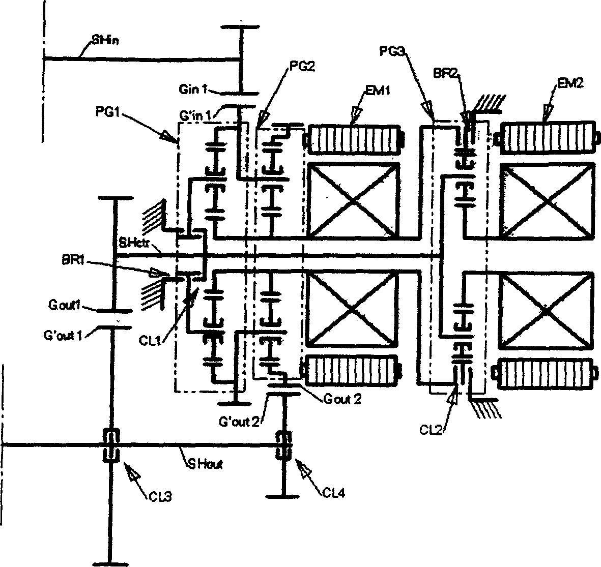
[0038] Such as image 3 , Figure 4 As shown, the continuously variable transmission consists of three planetary gear trains (PG1, PG2, PG3), two motors (EM1, EM2), a motor controller (CTL) and a set of clutches (CL1, CL2, CL3, CL4, BR1, BR2) composition. The program also includes an input shaft (SH in ) an output shaft (SH out ) and several pairs of gears (G in 1, G' in 1, G out 1, G' out 1, G out 2, G' out 2). Each planetary gear train consists of a ring wheel (R1, R2, or R3), a sun gear (S1, S2, or S3), a set of planetary gears (P1, P2, or P3), and a planetary gear carrier ( C1, C2, or C3) composition. Each motor consists of a rotor (RT1 or RT2) and a stator (ST1 or ST2). Each pair of input gears and each pair of output gears consists of a driving wheel and a driven wheel, the driving wheel is represented by G; the driven wheel is represented by G'.

[0039] When used in electromechanical hybrid vehicles, the solution also includes a accumulator (BT) for the st...

Embodiment 2

[0104] As shown in Figure 7, compared with Embodiment 1, a pair of output gears (G out 3 and G out ’3) and a clutch (CL5). Correspondingly, an additional speed zone for compound power splitting is added. In other words, this embodiment can provide four forward zones and one retrograde zone. The four forward zones include an output power split speed zone and three composite power split speed zones.

[0105] Output gear pair (G out 3, G' out 3) The driving gear (G out 3) with the center shaft (SH ctr ) connected, connected to the second branch of the five-branch system, the driven wheel (G out ’3) through the clutch (CL5) and the output shaft (SH out ) to make selective connections. Except for the compound power split speed zone added at the end, the working state of the motor in other speed zones and the clutch situation of the clutch in the second embodiment are exactly the same as those in the first embodiment. Therefore, no further retelling. The following is only...

Embodiment 3

[0117] Such as Figure 8 As shown, similarly, if a pair of output gears (G out 4 and G' out 4) and a clutch (CL6), and the driving wheel of the output gear pair (G out 4) Connect to the fourth branch of the five-branch system where the third ring wheel (R3) is located, the driven wheel (G' out 4) Selectively connect with the output shaft (SH) through the clutch (CL6) out ) are coupled. Compared with embodiment 2, another speed zone of compound power split flow is obtained, that is, the fourth compound power split flow speed zone. According to the order of the overall forward speed zone, the speed zone of the composite power split is called the fifth speed zone.

[0118] The boundary point between the fourth speed zone and the fifth speed zone is the fourth speed node. The location of the fourth speed node is:

[0119] SR 4 = K 1 K ...


PUM


Abstract

The variable shift gear is composed of three coaxial planetary system, two motors, one controller, two power transmitting shaft and at least two clutches, each planetary system is comprised of at least three coaxial rotary components. The three planetary systems coupled into the five-branch system. The first branch is connected with the motor, the fifth branch is connected with the second motor, the third branch is connected with the first power transmitting shaft. The second shaft is selectively connected with the second or fourth branches. The two motors are conected electrically by controller and can transmit electric energy with each other.

Description

technical field [0001] The invention belongs to a high-efficiency energy-saving electromechanical hybrid stepless transmission, which can be widely used in various vehicles and power equipment. Background technique [0002] Internal combustion engines have a certain speed and power range, and within a small range to achieve the best operating conditions, or the lowest fuel consumption, or the lowest harmful emissions, or both. However, the actual road conditions are ever-changing, not only in the speed of the driving wheels, but also in the torque required by the driving wheels. Therefore, the speed and torque of the internal combustion engine, that is, the matching of the power state of the internal combustion engine and the power state of the driving wheel is one of the primary tasks of the transmission. [0003] A continuously variable transmission, whether mechanical, hydraulic, or electromechanical, can provide an infinite number of continuously selectable speed ratios...

Claims


Application Information

Patent Timeline
Patent Type & Authority Applications(China)
IPC IPC(8): B60K6/54F16H3/62F16H3/72F16H3/76F16H61/32
CPCF16H3/728
Inventor 江兵薛蕊薛忠和
Owner SHANDONG LIANCHENG GREENMAX TECH
Why Eureka
Try Eureka