Backlight modular
A technology of backlight module and light guide plate, applied in optics, nonlinear optics, instruments, etc., can solve problems such as large mixing distance
- Summary
- Abstract
- Description
- Claims
- Application Information
AI Technical Summary
Problems solved by technology
Method used
Image

Examples
no. 1 example
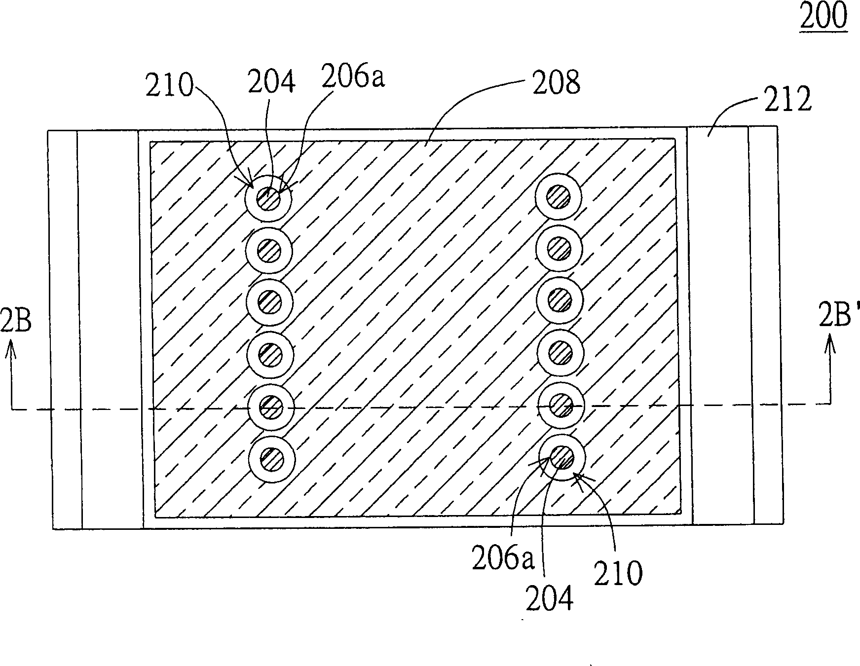
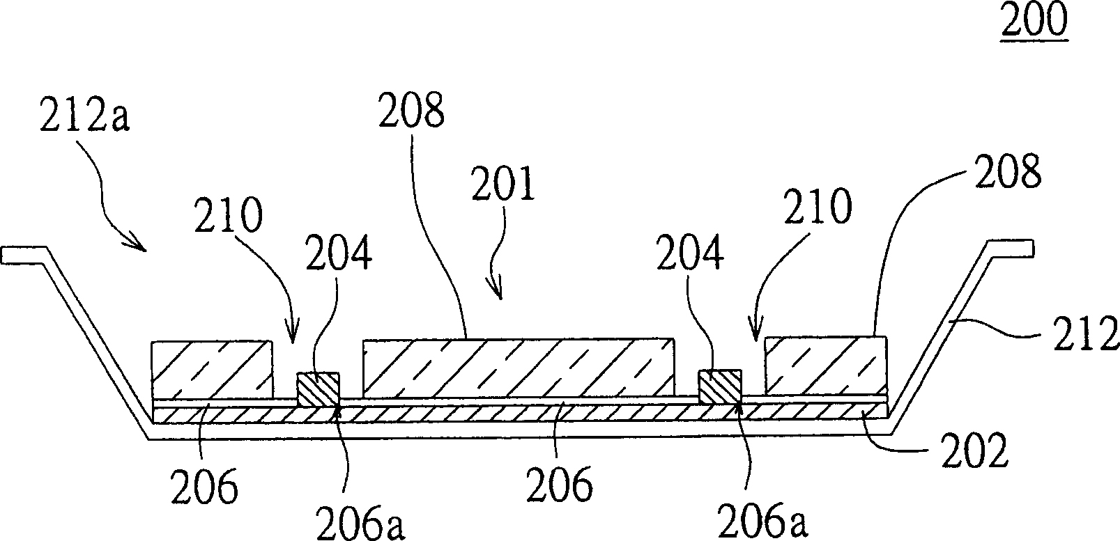
[0041] Please refer to Figure 2A and Figure 2B , Figure 2A It is a top view of the backlight module according to the first embodiment of the present invention, Figure 2B is along Figure 2A The cross-sectional view of the backlight module viewed by the section line 2B-2B' in .
[0042] The backlight module 200 includes a light mixing device 201 and a frame 212 . An accommodating space 212a is formed in the frame 212, and the accommodating space is surrounded by the bottom plate of the frame and the side plates of the frame, and the light mixing device 201 is disposed in the accommodating space 212a.
[0043] The light mixing device 201 at least includes a circuit board 202 , a plurality of LEDs 204 and a light guide plate 208 . The LEDs 204 are electrically connected to the circuit board 202 and protruded on the circuit board 202 . The LEDs 204 are used to provide the light required by the backlight module 200 . Wherein, these light emitting diodes 204 are, for examp...
no. 2 example
[0049] Please refer to image 3 , which is a side view of the backlight module according to the second embodiment of the present invention. The difference between the backlight module 300 of this embodiment and the backlight module 200 of the first embodiment is that the backlight module 300 further includes at least one diffusion structure 302 and an optical film 304 . As for other identical components, the same reference numerals are used and will not be repeated here.
[0050] The diffusion structure 302 is disposed on the light guide plate 208 to seal the opening 210 and is located above the LEDs 204 . The diffusion structure 302 diffuses the light above the light emitting diodes 204 to avoid local bright bands and increase the overall light mixing effect.
[0051]The optical film 304 is used to receive the light from the light guide plate 208 and the reflective material on the side wall of the frame 212, and further diffuse and mix the light. In this way, while reducin...
no. 3 example
[0054] Please refer to Figure 5 , which is a top view of the backlight module according to the third embodiment of the present invention. exist Figure 5 Among them, the difference between the backlight module 500 of this embodiment and the backlight module 200 of the first embodiment lies in the shape of the opening 504 of the light guide plate 502 .
[0055] These light emitting diodes 204 form several rows of light source groups, such as two rows of light source groups 204a, and the openings on the light guide plate 502 are several grooves, such as Figure 5 There are two grooves 504 shown in , each groove 504 accommodates a row of light source groups 204a. In addition, in this embodiment, at least one diffusion structure can be provided to seal the grooves 504, the diffusion structure is located above the light source group 204a, and the diffusion structure can be a structure of any shape.
PUM
 Abstract
Description
Claims
Application Information
 - R&D
- Intellectual Property
- Life Sciences
- Materials
- Tech Scout
- Unparalleled Data Quality
- Higher Quality Content
- 60% Fewer Hallucinations
Browse by: Latest US Patents, China's latest patents, Technical Efficacy Thesaurus, Application Domain, Technology Topic, Popular Technical Reports.
© 2025 PatSnap. All rights reserved.Legal|Privacy policy|Modern Slavery Act Transparency Statement|Sitemap|About US| Contact US: help@patsnap.com