Combining method for heat pipes and radiating fins

A technology of heat dissipation fins and heat pipes, which is applied in the field of combination of heat pipes and heat dissipation fins, can solve problems such as unstable combination of heat pipes and heat dissipation fins, troublesome assembly process of radiators, etc., and achieves improved operation efficiency and convenience, The effect of high-efficiency thermal conductivity and small interface thermal resistance

Inactive Publication Date: 2005-01-19
HONG FU JIN PRECISION IND (SHENZHEN) CO LTD +1
View PDF1 Cites 5 Cited by
  • Summary
  • Abstract
  • Description
  • Claims
  • Application Information

AI Technical Summary

Problems solved by technology

However, due to the mechanical contact between the heat pipe 140 and the heat dissipation fins 160, there are gaps, which cannot be evenly sealed. Therefore, the heat transfer effect between the heat pipe 140 and the heat dissipation fins 160 is relatively poor, and the high conductivity of the heat pipe 160 cannot be fully obtained. play, the overall performance of the radiator 100 is affected, and this method cannot utilize the formed heat pipe to assemble the radiator
[0004] In order to assemble the heat sink with formed heat pipes and make the heat pipes and heat dissipation fins evenly bonded without gaps, some companies use heat-conducting adhesive bonding, but due to the low bonding strength of heat-conducting adhesives, the combination of heat pipes and heat-dissipating fins is difficult. stable
Therefore, most manufacturers now use soldering to weld the heat pipes and heat dissipation fins together. Firstly, the heat dissipation fins are provided with perforations with folded edges. One method is to arrange the heat dissipation fins in sequence. Then it is perforated to form a channel, apply solder paste in the channel, and then put the heat pipe through the channel, and use the solder paste to weld the heat pipe and the heat dissipation fins together, but it is more difficult to apply solder paste on the inner wall of the long tubular channel. It is not easy, and it is easy to scratch the solder paste during the threading process of the heat pipe, so that the solder paste cannot be completely and evenly filled in the gap between the heat pipe and the heat dissipation fins; another method is to put the heat dissipation fins on the heat pipe one by one, When each cooling fin is installed on the heat pipe, apply solder paste on its folded edge, and then put another cooling fin on it. Since the paste is applied at intervals from the installation of the cooling fin, the assembly process is troublesome and the efficiency is low. It is quite low, and this method is likely to cause the solder paste to be squeezed and overflow, resulting in a decrease in utilization rate, which in turn affects the combination effect of the heat pipe and the heat dissipation fin

Method used


Image

  • Combining method for heat pipes and radiating fins
  • Combining method for heat pipes and radiating fins
  • Combining method for heat pipes and radiating fins

Examples


Embodiment Construction

[0015] The method for combining heat pipes and cooling fins of the present invention is applied to the manufacture of heat pipe radiators, which can quickly and closely connect the formed heat pipes and cooling fins, and make the heat pipe radiators have high-efficiency heat conduction performance.

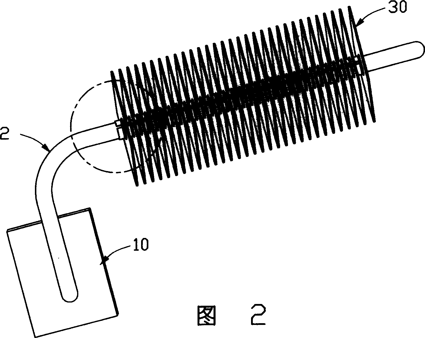
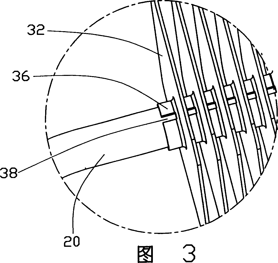
[0016] Please refer to Fig. 2, this heat pipe type radiator 1 has a base 10 which is in contact with heating electronic components such as a central processing unit, at least one heat pipe 20 is horizontally inserted on the base 10, and several heat dissipation fins 30 are parallel at certain intervals. Arranged and threaded on the heat pipe 20 , the heat sink 1 can absorb the heat generated by the heat-generating electronic components from the base 10 , and transfer the heat from the heat pipe 20 to the heat dissipation fins 30 , and then dissipate it. Of course, this heat sink 1 is not limited to the above-mentioned structure. For example, the heat pipe 20 can be inserted vertica...


PUM


Abstract

The invention provides a combining method for a heat pipe and a radiating fin. A threading hole is arranged on radiating fin body. At fringe of the threading hole is arranged an edgefold with a notch. The radiating fin is used to thread the heat pipe through the threading hole, and heatconducting tin paste is smeared at the notch. Then combination of the radiating fin and the heat pipe is placed in high temperature environment to be heated, and is divorced from the high temperature environment. The radiating fin and the heat pipe will be welded together after cooling.

Description

【Technical field】 [0001] The invention relates to a method for combining heat pipes and heat dissipation fins, in particular to a method for quickly and conveniently combining heat pipes and heat dissipation fins evenly and tightly by using solder paste. 【Background technique】 [0002] The computer has become an indispensable tool in many industries. With the continuous improvement of its demand, the computer industry has developed rapidly and by leaps and bounds. The performance of the computer depends largely on the central processing unit, whose speed and stability directly affect the performance of the whole machine. Performance, the higher the integration of the central processing unit and the faster the running speed, the greater the heat generated with it. If the heat is not dissipated in time, the heat will accumulate and the temperature will rise, which will greatly affect the stability of its operation. Therefore, it is necessary to dissipate the heat generated by ...

Claims


Application Information

Patent Timeline
Patent Type & Authority Applications(China)
IPC IPC(8): F28D15/02
Inventor 李学坤陈俊吉吴宜强
Owner HONG FU JIN PRECISION IND (SHENZHEN) CO LTD
Why Eureka
Try Eureka