Method for repairing defects of electrode pattern

An electrode pattern and defect technology, applied in the field of repairing defects, can solve problems such as poor electrode discharge effect, deterioration of plasma display display effect, and scrapping.

Inactive Publication Date: 2005-01-19
AU OPTRONICS CORP
View PDF0 Cites 8 Cited by
  • Summary
  • Abstract
  • Description
  • Claims
  • Application Information

AI Technical Summary

Problems solved by technology

However, as the precision of the electrode pattern continues to increase and the line width becomes smaller and smaller, the electrode pattern is prone to defects due to the existence of particles or scratches on the mask, resulting in the maintenance of the electrode at the predetermined startup. The discharge cannot be stabilized after the voltage is applied, or the abnormal discharge of the sustaining electrode is caused without the starting voltage
[0005] The electrode pattern defect of the plasma display leads to the poor discharge effect of the electrode, which deteriorates the display effect of the plasma display. However, there is currently no relevant solution to the defect caused by the electrode pattern making
Manufacturers often adopt looser quality control standards in order to improve the yield rate and avoid a large increase in cost, but even so, there are still a considerable proportion of plasma displays that seriously affect the quality of plasma displays due to excessive electrode pattern defects, or even scrap them, seriously affecting the quality of plasma displays. Plasma Display Capacity
Therefore, for plasma displays with extremely high costs, how to solve the defects of electrode patterns to improve the stability of electrode discharge is a very important issue in the research and development of plasma displays.

Method used


Image

  • Method for repairing defects of electrode pattern
  • Method for repairing defects of electrode pattern
  • Method for repairing defects of electrode pattern

Examples


Embodiment Construction

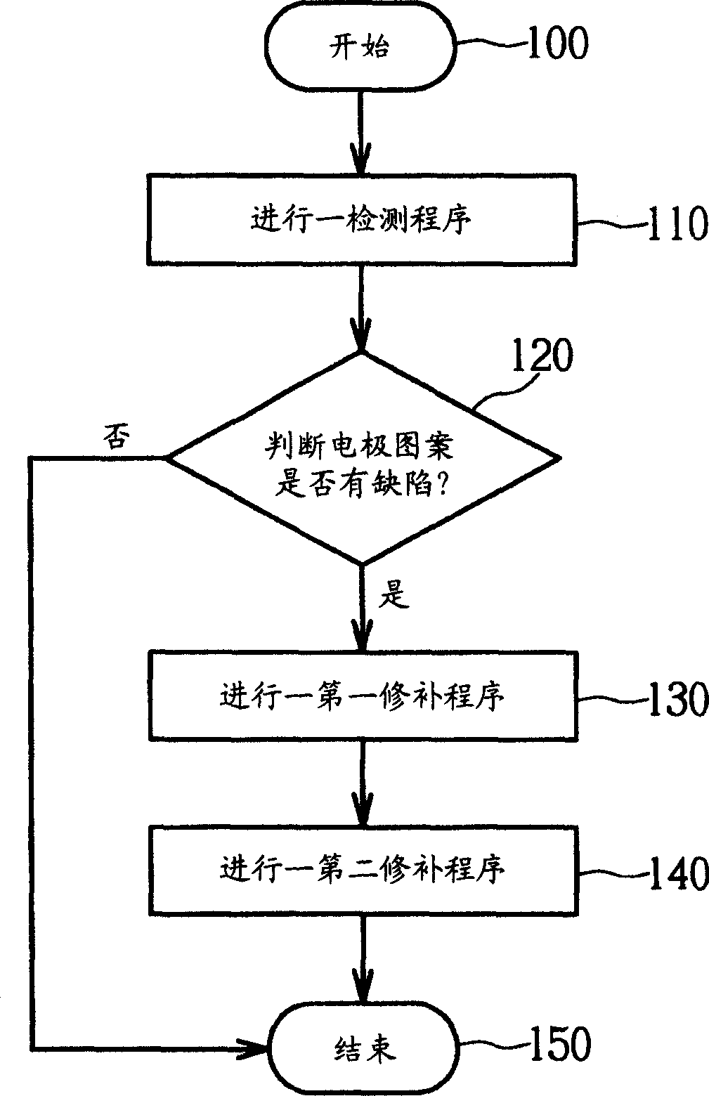
[0027] Please refer to figure 1 , figure 1 It is a flowchart of the method for repairing electrode pattern defects of the present invention. Such as figure 1 As shown, the method for repairing electrode pattern defects of the present invention includes the following steps:

[0028] Step 100: Start;

[0029] Step 110: Perform a detection procedure to detect the electrode pattern of the plasma display;

[0030] Step 120: Determine whether the electrode pattern is defective, repair it if there is a defect, and end the repair process if there is no defect;

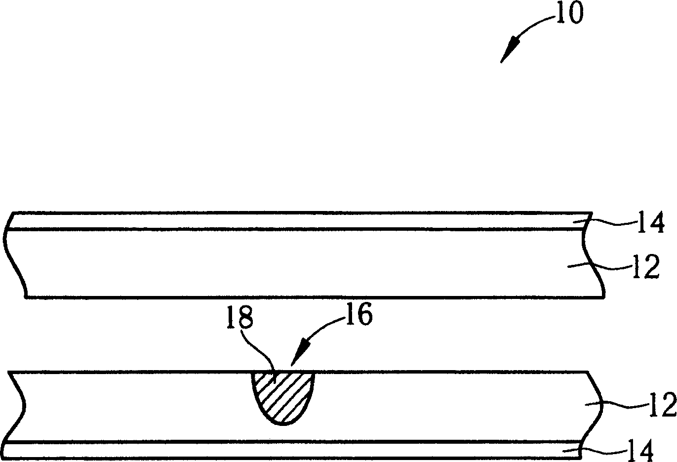
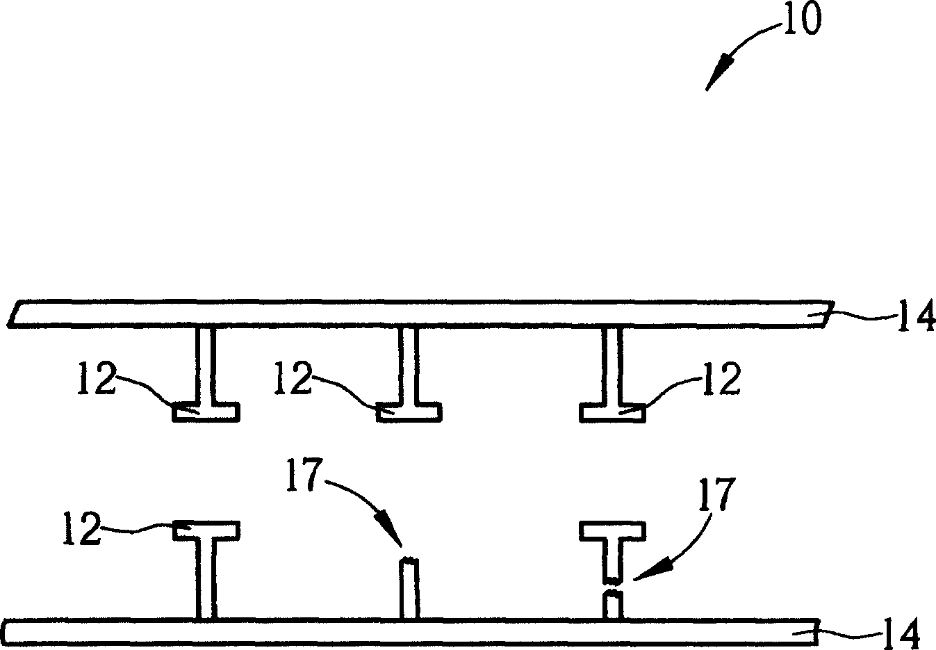
[0031] Step 130: Perform a first repair procedure to fill the recessed part of the electrode pattern;

[0032] Step 140: Perform a second repair procedure to remove the protruding part of the electrode pattern; and

[0033] Step 150: End.

[0034] As mentioned above, the method for repairing electrode pattern defects of the present invention is to perform a detection procedure after the production of the plasma display electrod...


PUM


Abstract

The invention provides a method of repairing the defects in an electrode pattern, containing: executing a detecting program to detect if the electrode pattern on the plasma display has defects, executing a first repairing program to fill the sunk parts and executing a second program to eliminate the raised parts. In the first repairing program, it uses conductive plasma to fill the sunk parts and in the second one, uses a laser beam to eliminate the raised parts, so as to give full play to stable discharge of the electrode.

Description

Technical field [0001] The present invention provides a method for repairing defects, especially a method for repairing electrode pattern defects by using conductive materials and laser beams. Background technique [0002] With the development of the electronic information industry, the application and demand for flat panel displays (FPD) continue to expand. Among them, plasma display panes (PDP) have been developed due to their small size, large size, and wide viewing angle. It has become a product with great development potential in flat panel displays. [0003] The plasma display mainly includes a front substrate, a back substrate, an ionized gas (not shown) filled between the front substrate and the back substrate to generate ultraviolet rays, and a plurality of pairs of sustain electrodes parallel to each other ( The sustain electrode) is set on the surface of the front substrate for discharge. The front substrate further includes a plurality of auxiliary electrodes (bus ele...

Claims


Application Information

Patent Timeline
Patent Type & Authority Applications(China)
IPC IPC(8): H01J9/02H01J9/42H01J9/50
CPCY02W30/82
Inventor 吴逸人
Owner AU OPTRONICS CORP
Why Eureka
Try Eureka