Door lock switch

A door lock switch and switch technology, which is applied to other washing machines, washing devices, textiles and papermaking, etc., can solve the problems of short locking and unlocking time and long unlocking time

Inactive Publication Date: 2005-01-26
HANGZHOU KAMBAYASHI ELECTRONICS
View PDF3 Cites 18 Cited by
  • Summary
  • Abstract
  • Description
  • Claims
  • Application Information

AI Technical Summary

Problems solved by technology

[0009] The present invention aims to solve the problems that the lock and unlock time of the door lock applicable to the European type drum washing machine is relatively long, and that the lock of the door body will be unlocked when the power is turned off abnormally, which may cause overflow of clothes and water in

Method used


Image

  • Door lock switch
  • Door lock switch
  • Door lock switch

Examples


Embodiment 1

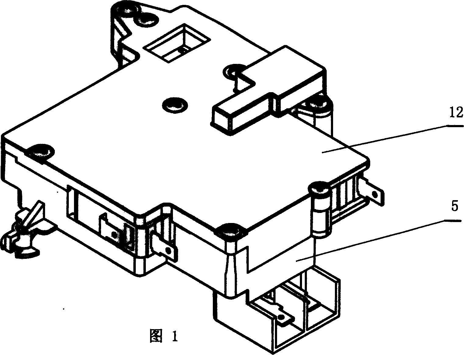
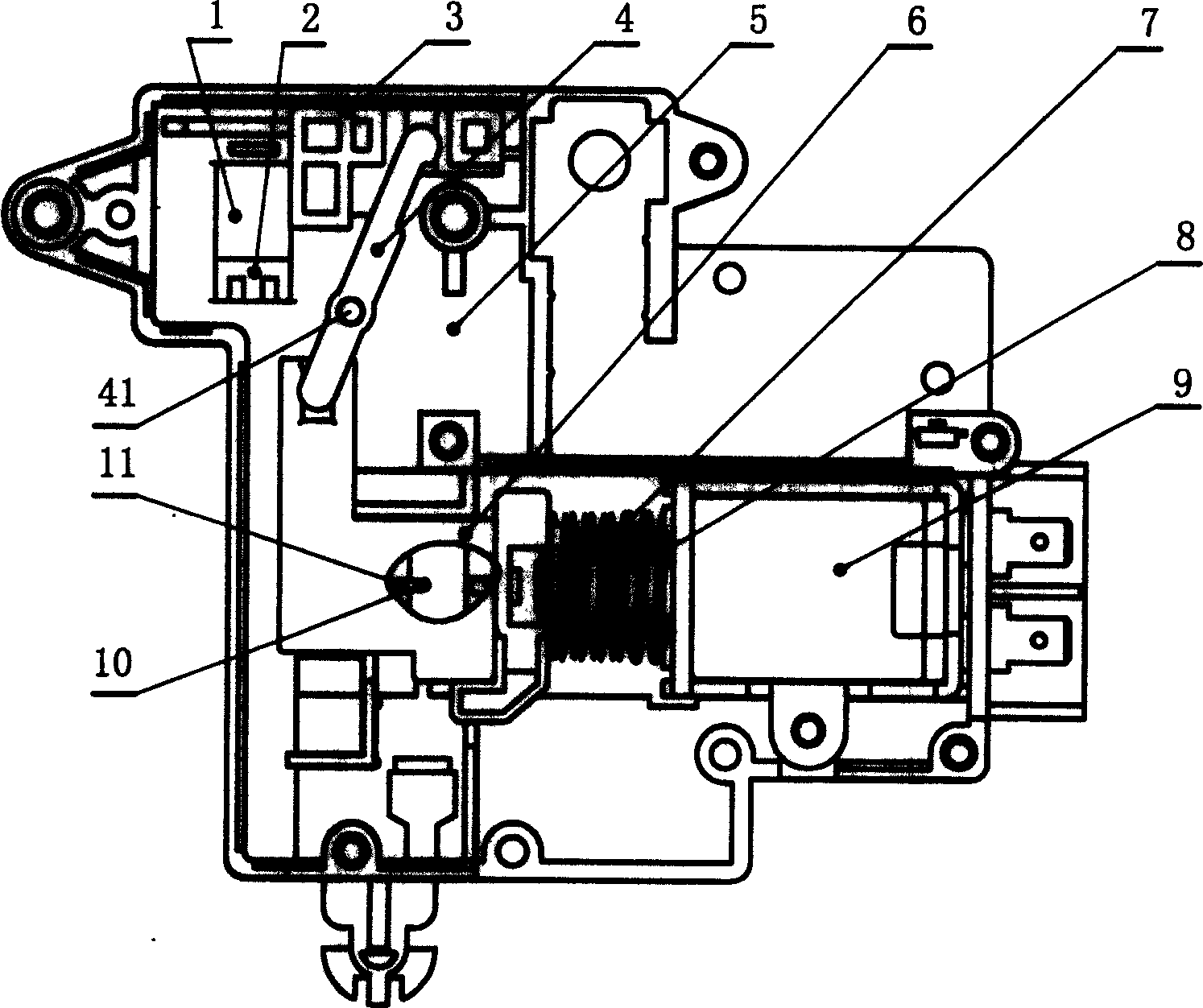
[0030] This example door lock switch, see Figure 1, figure 2, with a base body 5 and a cover plate 12 with a hook hole 1, a buckle edge 2 is provided under the hook hole, an electromagnetic coil 9 and an operating slide plate 6 are arranged inside the base body 5, an iron core 8 is connected to the operating slide plate 6, and a spring 7 is sheathed on the periphery of the base body 5 Located between the electromagnetic coil and the operating slide plate, the inner surface of the operating slide plate 6 is provided with a "positioning / resetting" guide groove 11, and a positioning pin 10 is provided, the fixed end 101 of which is connected to the base body 5, and the other end is located in the guide groove 11, and the base body 5 is provided with a There is a slider 3 located in the inner direction area of ​​the upper part of the hook hole 1, and the middle part of the lever 4 is pivotably sleeved on the fulcrum pin 41, and the inner protrusion of one end of the lever 4 is embe...

Embodiment 2

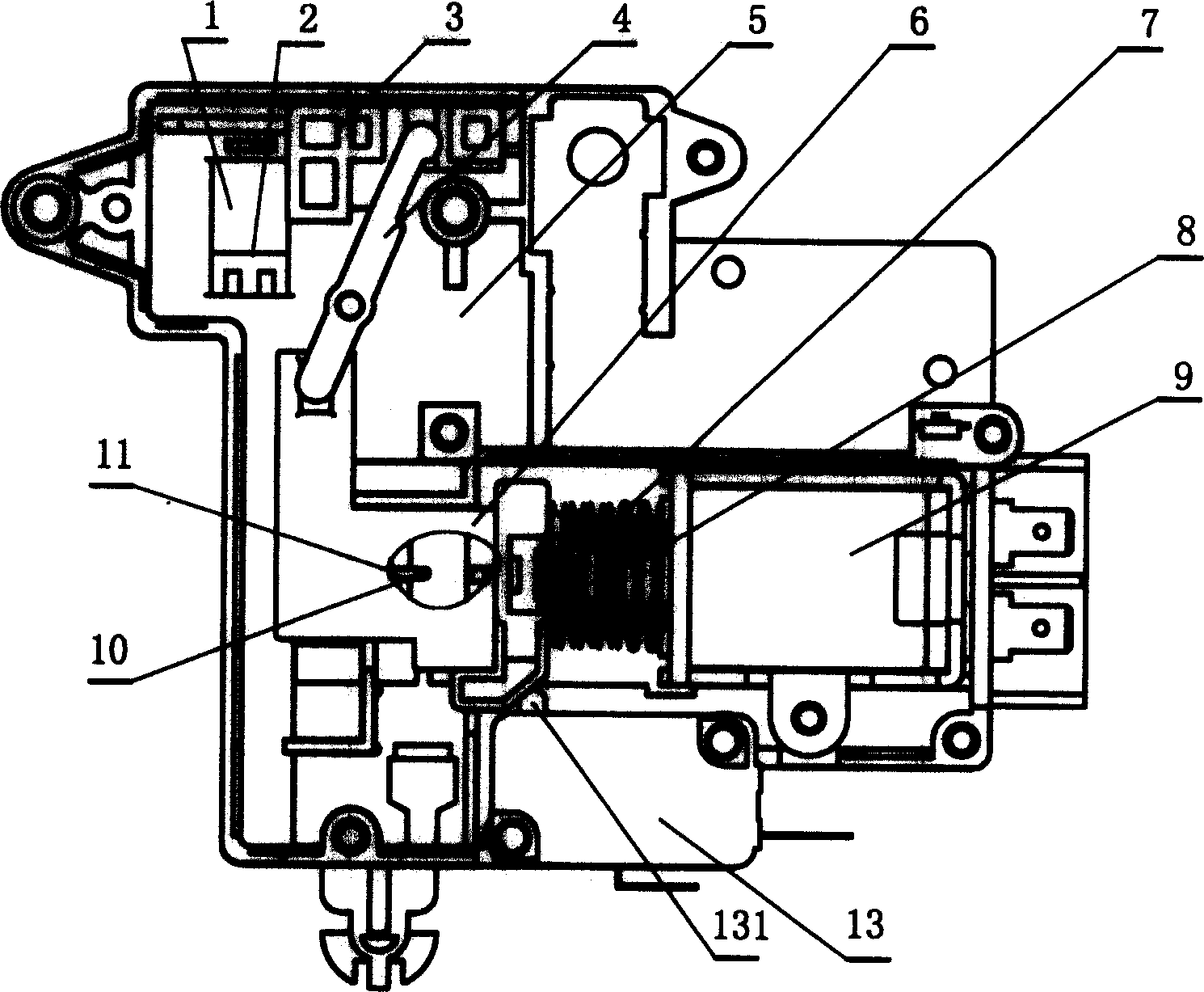
[0033] This example door lock opening, see image 3 , The base body 5 is provided with a microswitch I 13 whose inner side is provided with a contact 131, and one end of the operation slide plate 6 corresponding to the contact 131 is provided with a slope. Other structures are the same as the above example.

[0034] When the electromagnetic coil energized operation slide plate was sucked and positioned, the microswitch I 13 contacts 131 retracted under the pressure of its inclined plane, which can generate a locking signal.

Embodiment 3

[0036] For this example door lock switch, see Figure 4 , Figure 9, Figure 10 , the base body 5 is provided with a button 17, a micro switch II 18 and a leaf spring 19. One end of the leaf spring 19 is a fixed end 192 connected to the base body 5, and the other end is connected with a bevel plate 191. One end of the button 17 has a convex post 171 located on the base body 5 The through hole protrudes outward from the back of the base body 5. The other end of the button 17 is the abutting end 172 against the inclined plate 191. The side of the micro switch II 18 and the leaf spring 19 is provided with a contact 181. The button 17 The inner surface is topped with a spring 21 corresponding to the boss 171 . The base body 5 is provided with a manual unlocking plate 16 , the inner end of which is provided with a slot hole 161 to cover the positioning pin 10 . Other structures are the same as in Example 1.

[0037] After the door is closed, push the button 17 to move inward thro...


PUM


Abstract

Locking reliable also can fixed reconciliation locks or fast door interlock switch, has opens dog hole (1) substrate (5) and lap (12), the substrate (5) in is equipped with the magnet coil (9) and the operation slide (6), operates the slide (6) on the company to have the ferrite core (8) besides the jacket to have the spring (7) to be located the magnet coil between the operation slide, operates the slide (6) in to be equipped with 'the localization/replacement' guide way (11), is equipped with the guide pin (10) its end to fix to the substrate (5), another end is located guide way (11), The substrate (5) in is equipped with the slide (3) to be located dog hole (1) upside within the side direction region, is equipped with the release lever (4) its middle to be possible the pivot shaft change of scene set to the fulcrum pin (41), the release lever (4) an end AND-OPERATION slide (6) is connected, another end and the slide (3) unite. This invention mainly is suitable for rotary drum washer door lock locking and the solution lock.

Description

technical field [0001] The invention relates to a locking and unlocking device of a door lock, in particular to a locking and unlocking device after the door body of a drum washing machine is fastened. Background technique [0002] At present, the locking and unlocking device of the drum washing machine door produced in China, that is, the door lock switch, generally adopts this door lock switch technology of European countries. This kind of door lock has a slide plate on its lock hook, and a button hole is opened on the slide plate, and the slide block can be embedded in or leave the button hole of the slide plate; after the lock hook is buckled in, the lock hook is locked when the slider is inserted into the button hole of the slide plate , at this time, the lock hook cannot be released manually. When the slider leaves the button hole of the slide plate, the lock of the lock hook is released, and the lock hook can be released manually. In this door loc...

Claims


Application Information

Patent Timeline
IPC IPC(8): D06F37/42
Inventor 瞿卫王华
Owner HANGZHOU KAMBAYASHI ELECTRONICS
Why Eureka
Try Eureka