Current starved DAC-controlled delay locked loop

A delay-locked loop, control logic technology, applied in the direction of automatic power control, electrical components, generation of electrical pulses, etc.

Inactive Publication Date: 2006-12-20
ATMEL CORP
View PDF4 Cites 4 Cited by
  • Summary
  • Abstract
  • Description
  • Claims
  • Application Information

AI Technical Summary

Problems solved by technology

Additionally, the control circuit m

Method used


Image

  • Current starved DAC-controlled delay locked loop
  • Current starved DAC-controlled delay locked loop
  • Current starved DAC-controlled delay locked loop

Examples


Embodiment Construction

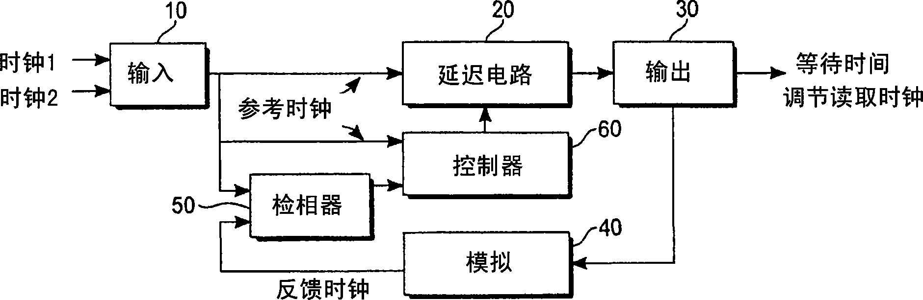
[0020] The present invention uses a digitally controlled delay locked loop to establish a fixed time through the delay cell circuit. A reference signal (eg, a square wave with a desired delay period through the circuit) is fed into the phase detector. The phase detector provides a high going pulse to the delay circuit. The detector then determines which comes first: the next pulse in the reference signal, or the output from the delay circuit. The digital accumulation register toggles state based on the previously determined result. The accumulation register feeds the digital-to-analog converter, which provides the current reference for the delay circuit.

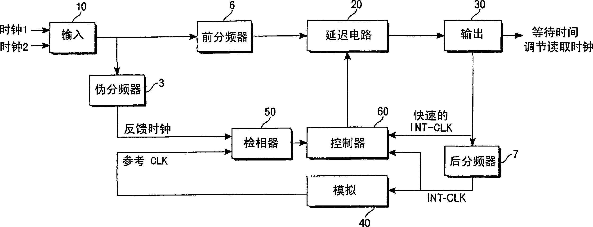
[0021] The present invention demonstrates several design features which provide improved properties over the prior art. One of the eight pulses from the phase detector is given to the delay circuit. This removes any possibility of locking onto a wrong response, since the delay circuit will not have a pulse in it when the...


PUM


Abstract

A delay locked loop circuit with improved restart features. The circuit includes a clock input (1120, a clock output (116), a divider circuit (114), phase detector (118) and control logic (124). The circuit includes a means (126) for implementing a binary search of outputs from the control logic (124) for generating a calibration bit, which is applied to the transmission on an output line (120).

Description

technical field [0001] The present invention relates to semiconductor circuits, and more particularly to an improved delay locked loop (DLL) design for power savings and fast shutdown and restart. Background technique [0002] The design of current controlled delay cells is relatively well known in the art. A pair of cascaded CMOS inverters, with an additional p-type and n-channel transistor inserted into the current path and reflected from the reference current, will establish a fixed delay through a cell. No matter how a conventional current-controlled DLL is designed, it has many disadvantages. The current value must be accurate and must match the delay circuit. Short delays for input signals require high operating currents. To compensate for other variations, such as voltage supply or temperature variations, high value current mirrors are required. These features increase power requirements. In addition, these systems suffer from noise interference. [0003] Under ...

Claims


Application Information

Patent Timeline
IPC IPC(8): H03L7/081H03L7/08H03L7/18H03K3/017
Inventor D·J·迈耶
Owner ATMEL CORP
Why Eureka
Try Eureka