
Circuit structure and method for realizing clock recovery on the basis of USB device

A technology of clock recovery and circuit structure, which is applied in the field of clock recovery and USB device clock recovery, can solve the problems of peripheral complexity, large circuit area, poor jitter suppression performance, etc., achieve a wide range of applications, simplify peripheral circuits, and reduce product costs. Effect

Active Publication Date: 2016-02-17
CRM ICBG (WUXI) CO LTD
View PDF4 Cites 4 Cited by
  • Summary
  • Abstract
  • Description
  • Claims
  • Application Information

AI Technical Summary

Problems solved by technology

[0007] (1) External crystal oscillator, the periphery is relatively complex, the error is large, and the cost is increased;
[0008] (2) The PLL design of the phase-locked loop makes the circuit area relatively large, the overall design is difficult, the locking time is long, it is sensitive to noise, and there are problems such as accumulation of phase difference errors;
[0009] (3) Delay-locked loop DLL design has poor jitter suppression performance, relatively limited locking range, high power consumption, and no frequency tracking characteristics

Method used


Image

  • Circuit structure and method for realizing clock recovery on the basis of USB device
  • Circuit structure and method for realizing clock recovery on the basis of USB device
  • Circuit structure and method for realizing clock recovery on the basis of USB device

Examples


Embodiment Construction

[0056] In order to describe the technical content of the present invention more clearly, further description will be given below in conjunction with specific embodiments.

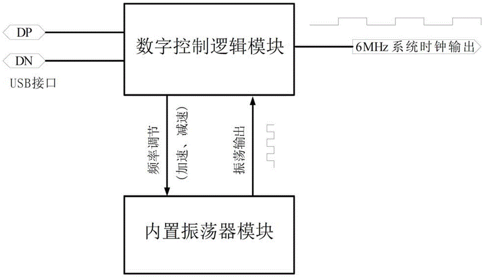
[0057] The present invention is mainly composed of a built-in oscillator module and a digital control logic module, such as figure 1 shown.

[0058] The built-in oscillator module is used to generate an oscillation signal much higher than 1.5MHz as the clock signal of the digital control logic module;

[0059] The digital control logic module is firstly used to sample the clock signal generated by the built-in oscillator module for the duration of the 4th and 5th bits (sampling bits) of the USB interface synchronous signal to complete clock recovery; secondly, the digital control logic module also compares the USB data Transmission frequency and the frequency of the built-in oscillator, automatically switch the frequency of the built-in oscillator between low speed, medium speed and high speed.

[0060] T...


PUM


Abstract

The invention relates to a circuit structure and method for realizing clock recovery on the basis of a USB device. The circuit structure comprises a built-in oscillator module for generating oscillation signals; and a digital control logic module which includes a USB clock recovery unit for sampling the oscillation signals of the built-in oscillator and performing the clock recovery and a frequency adjustment unit for adjusting the oscillation frequency of the built-in oscillator according to a comparison result between USB signals and the oscillation signals of the built-in oscillator. By using the circuit structure and method for realizing the clock recovery on the basis of the USB device through such a structure, an accurate system clock can be generated, a frequency tracking feature is exhibited, a USB data transmission frequency is compared with the frequency of the built-in oscillator through adoption of the digital control logic module, the frequency of the built-in oscillator is automatically switched among a low-speed state, a medium-speed state and a high-speed state, the system precision and the stability are guaranteed, the production cost is decreased, and the application scope is wider.

Description

technical field [0001] The present invention relates to the field of clock recovery, in particular to the field of USB device clock recovery, in particular to a circuit structure and method for realizing clock recovery based on USB device. Background technique [0002] Most of the existing technologies are the following solutions: [0003] (1) Using an external crystal oscillator to provide an accurate clock for the circuit; [0004] (2) A phase-locked loop PLL design is adopted to generate a clock signal consistent with the frequency and phase of the serial data; [0005] (3) Adopt delay-locked loop DLL design to generate a clock signal consistent with serial data frequency and phase. [0006] Disadvantages of the above approach: [0007] (1) External crystal oscillator, the periphery is relatively complex, the error is large, and the cost is increased; [0008] (2) The PLL design of the phase-locked loop makes the circuit area relatively large, the overall design is mo...

Claims


Application Information

Patent Timeline
Patent Type & Authority Applications(China)
IPC IPC(8): H03K5/13
Inventor 黄燕曹旺
Owner CRM ICBG (WUXI) CO LTD
Learn More