Vehicle-drive control device and method and program therefor

A vehicle and processing device technology, applied in control devices, battery/fuel cell control devices, power devices, etc., can solve problems such as discomfort, inability to stop the engine, and shocks

Active Publication Date: 2005-02-02
AISIN AW CO LTD
View PDF2 Cites 25 Cited by
  • Summary
  • Abstract
  • Description
  • Claims
  • Application Information

AI Technical Summary

Problems solved by technology

[0018] This makes it more difficult to bring the crankshaft to the target stop position at the end of the brake control, making it impossible to stop the engine at the target stop position
[0019] Furthermore, if the engine cannot be stopped at the target stop position, the generator must be driven to rotate the crankshaft at a predetermined time after the engine stops, which will cause shock and discomfort to the occupants of the vehicle.

Method used


Image

  • Vehicle-drive control device and method and program therefor
  • Vehicle-drive control device and method and program therefor
  • Vehicle-drive control device and method and program therefor

Examples


Embodiment Construction

[0098] Embodiments of the present invention will be described in detail below with reference to the accompanying drawings. In this case, a vehicle drive device mounted on a hybrid vehicle as a vehicle, and a hybrid vehicle drive control device as a vehicle drive control device that performs the control will be described.

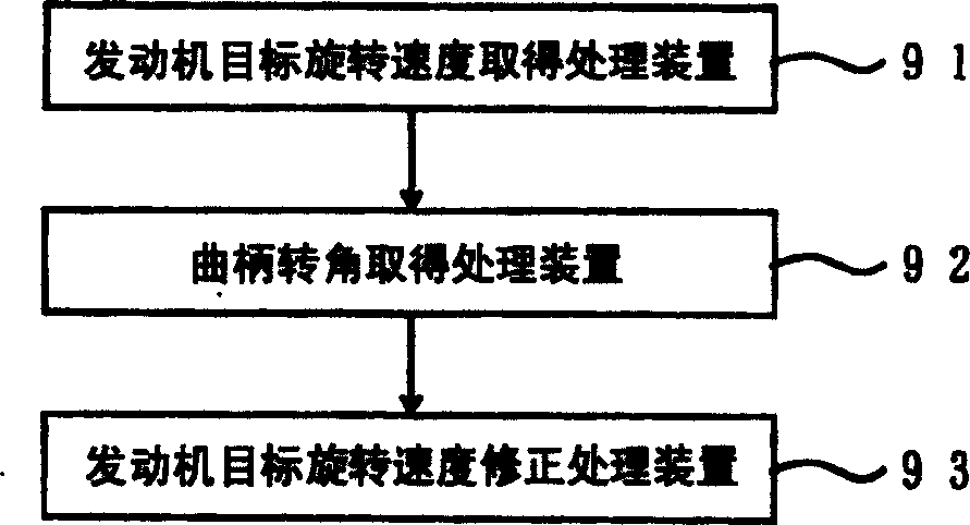
[0099] figure 1 is a functional block diagram of the drive control device for a hybrid vehicle in the first embodiment of the present invention.

[0100] In the figure, 91 is an engine target rotational speed obtaining means for reducing the rotational speed of the engine and obtaining a target rotational speed representing a target value of the engine rotational speed required to stop the engine (not shown) at the target position. 92 is a crank angle obtaining processing means for obtaining a crank angle indicating the position of the crankshaft. 93 is an engine target rotational speed correction processing device for correcting the above-mentioned engin...


PUM


Abstract

The present invention includes a target-engine-speed acquisition means for acquiring a target engine speed necessary to reduce engine speed, thereby stopping the engine at a target stop position; a crank-angle acquisition means for acquiring a crank angle indicative of the position of a crankshaft; and a target-engine-speed correction means for correcting the target engine speed according to the acquired crank angle. Since the target engine speed is corrected according to the crank angle, the engine can be stopped at the target stop position even if the friction in the engine, the electric motor, etc. varies, even if the temperature or viscosity of the lubricating and cooling oils varies, or even if the vehicle is accelerated or decelerated during the reduction of the engine speed.

Description

technical field [0001] The present invention relates to a vehicle drive control device, a vehicle drive control method and a program thereof. Background technique [0002] Conventionally, in a vehicle drive device (drive train) in which a generator motor is provided between an engine and a transmission, the rotor of the generator motor is connected between the input shaft of the engine and the transmission, and in the radial direction of the rotor The outer side sets the stator. In addition, in the vehicle driving device, the generator motor can be used as a motor and driven, and the generated torque of the generator, that is, the generator torque can be transmitted to the engine to start rotation, or the generator motor can be driven. The generator motor is used as a generator, and generates electric energy by recovering the rotational energy of the rotor. [0003] Furthermore, in a vehicle driving device of a hybrid vehicle that is equipped with a planetary gear unit, a ...

Claims


Application Information

Patent Timeline
Patent Type & Authority Applications(China)
IPC IPC(8): B60W20/00B60K6/445B60L50/15B60W10/06B60W10/08B60W10/18F02D29/02F02D35/02F02D41/04F02D41/06F02D41/34F02D45/00F02N11/08
CPCF02D41/062F02D2200/501F02N15/003Y02T10/6239B60W10/06Y02T10/6286B60W2510/0685F02N11/0814F02D2041/0095B60W10/08F02N19/005Y02T10/48F02D2250/26B60W20/00F02D2200/0404F02D41/042F02N2019/008B60K6/445F02D41/009B60L7/14B60L15/20B60L15/2009B60L2210/40B60L2240/12B60L2240/36B60L2240/421B60L2240/423B60L2240/425B60L2240/441B60L2240/443B60L2240/445B60L2240/545B60L2240/547B60L2240/549B60L2240/80B60L2260/26B60L2270/145B60L50/61B60L50/16B60L58/12F02N11/04Y02T10/40Y02T10/62Y02T10/64Y02T10/70Y02T10/7072Y02T10/72F02D35/02B60W30/18018B60W20/10
Inventor 伊泽和幸久田秀树野村昌树山口幸藏大越利夫稻垣知亲长谷川和马
Owner AISIN AW CO LTD
Why Eureka
Try Eureka