Piezoelectric vibration gyro element, method for manufacturing the same, and piezoelectric vibration gyro sensor

A piezoelectric vibrating gyroscope and a manufacturing method technology, applied in piezoelectric devices/electrostrictive devices, manufacture/assembly of piezoelectric/electrostrictive devices, components of piezoelectric devices or electrostrictive devices, etc., It can solve problems such as reduced productivity and yield, overexposure, light source configuration change and troublesome positioning of masks, etc., to achieve the effect of ensuring symmetry and low cost

Inactive Publication Date: 2005-02-02
SEIKO EPSON CORP
View PDF7 Cites 3 Cited by
  • Summary
  • Abstract
  • Description
  • Claims
  • Application Information

AI Technical Summary

Problems solved by technology

However, since the irradiating angle of light on the slope portion 12a becomes smaller as described above, the burr forms a shadow, resulting in a part that cannot be completely or sufficiently exposed, and there is a high possibility that a part of the electrode film 15 remains without being etched.
[0021] In view of this situation, if in order to increase the exposure amount of the slope portion, increase the intensity of the irradiation light or prolong the exposure time, the portion other than the slope portion will be overexposed, and it is possible to form a correct pattern band for the photoresist film 16. to influence
In addition, although it is also possible to expose the slope part and other parts separately, it is necessary to prepare a separate exposure mask dedicated to the slope part and perform exposure separately, and operations such as changing the arrangement of the light source and correct positioning of the mask are cumbersome and increase man-hours. So it is possible to reduce productivity and yield

Method used


Image

  • Piezoelectric vibration gyro element, method for manufacturing the same, and piezoelectric vibration gyro sensor
  • Piezoelectric vibration gyro element, method for manufacturing the same, and piezoelectric vibration gyro sensor
  • Piezoelectric vibration gyro element, method for manufacturing the same, and piezoelectric vibration gyro sensor

Examples


Embodiment Construction

[0052] Hereinafter, best embodiments of the present invention will be described in detail with reference to the drawings.

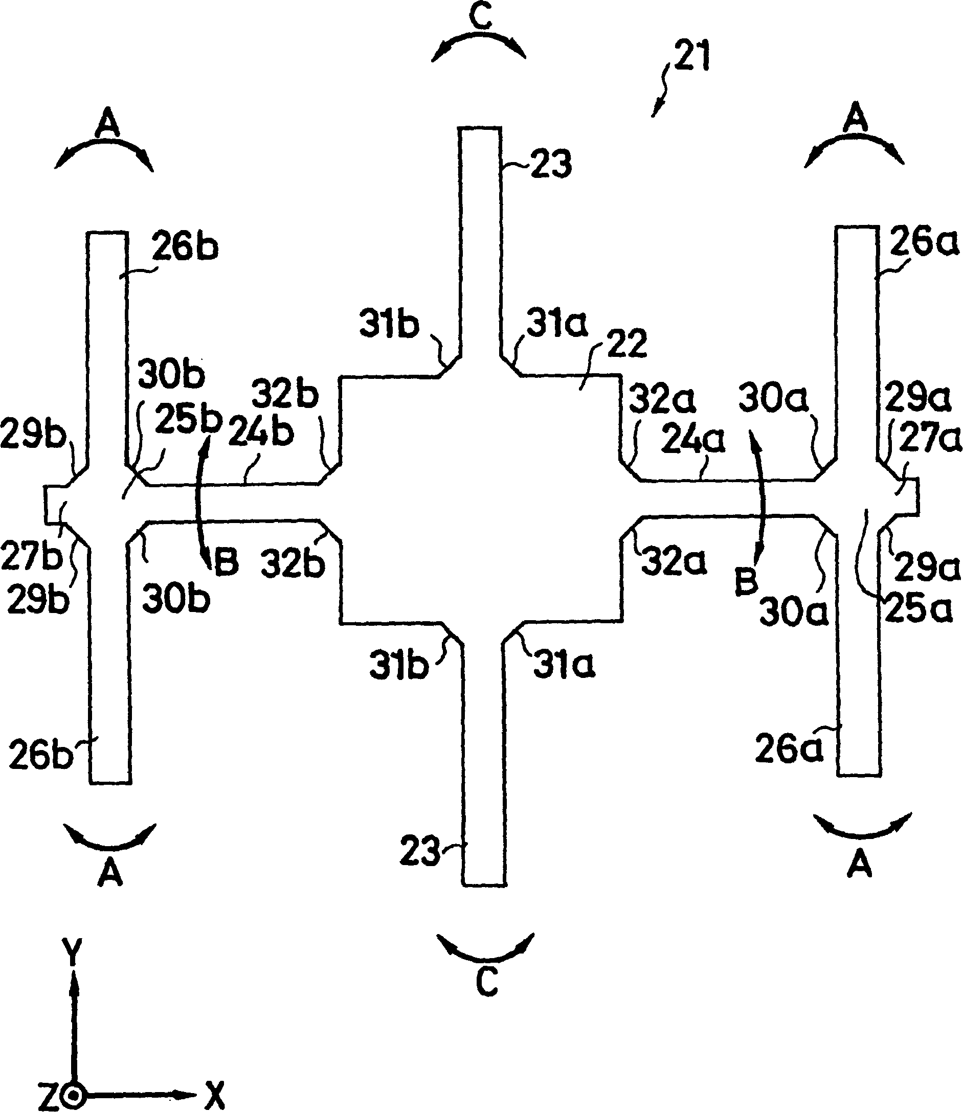
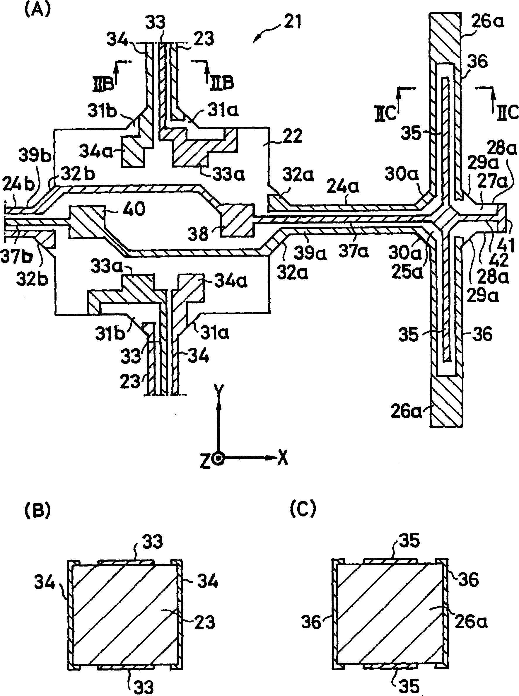
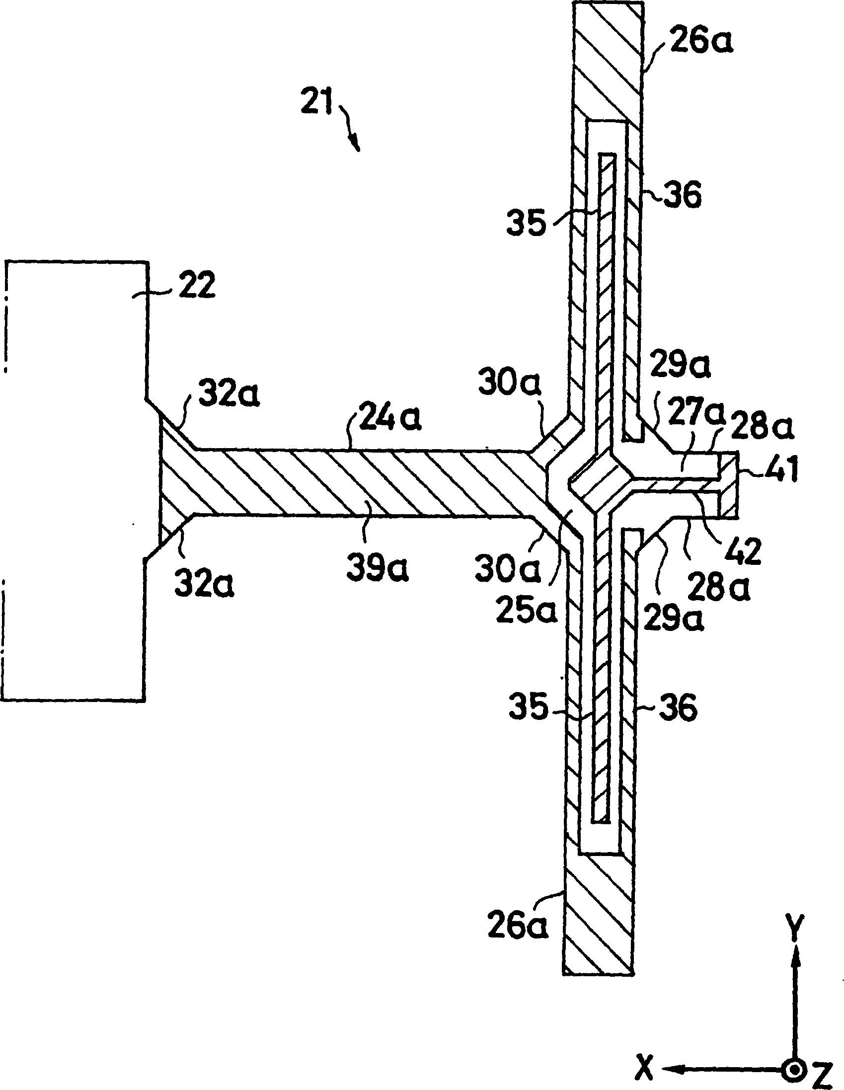
[0053] figure 1 The piezoelectric vibrating gyro element 21 of the present invention is schematically shown. The piezoelectric vibrating gyro element 21 has a pair of detection and vibrating arms 23 , 23 extending from the center of the upper and lower sides of the substantially square central support portion 22 to both upper and lower sides, respectively, as a detection vibration system. In addition, the piezoelectric vibrating gyro element 21 has, as a drive vibration system, a pair of connecting arms 24a, 24b extending from the center of the left and right sides of the central support part 22 to the left and right sides and in a direction perpendicular to the detection vibrating arm. and a pair of left and right driving vibrating arms 26a, 26a, 26b extending up and down on both sides in a direction perpendicular to the connecting arms and in parallel...


PUM


Abstract

To ensure a symmetric property of bending vibrations for vibrating arms, and to accurately and easily divide electrodes, in a piezoelectric vibrating gyroscope element provided with a pair of vibrating arms for detection at the center thereof and connecting arms on both sides thereof, and a pair of vibrating arms for drive at their tip parts. Planar parts 28a and 28b, oriented perpendicular to the direction of extension of the vibrating arms 26a and 26b for drive, are provided to both sides of the side surfaces of extension parts 27a and 27b extending further along the direction of extension of the tip parts of the connecting arms 24a and 24b from them. Wiring 42 is formed, in such a way, as to traverse the tip faces of the extension parts in the direction of their thickness and connect the tip parts of the connecting arms to the main front and back surfaces of the extension parts. First electrodes 35 and 35 in the main front and back surfaces of the vibrating arms for drive are electrically connected to each other. In an exposure process for dividing electrodes, the main surfaces and the side surfaces are simultaneously exposed obliquely from above perpendicular to the plane parts of the extension parts and at some angle from the perpendicular direction with respect to the main surfaces of the vibrating arms for driving.

Description

technical field [0001] The present invention relates to a piezoelectric vibrating gyro element having a driving vibrating arm and a detecting vibrating arm, a manufacturing method thereof, and a piezoelectric vibrating gyro sensor using the piezoelectric vibrating gyro element. Background technique [0002] Conventionally, piezoelectric vibrating gyroscopes have been widely used as rotational angular velocity sensors in attitude control and navigation systems of ships, airplanes, and automobiles, and in prevention and detection of hand shake in cameras, etc., and rotational direction sensors in 3D mice, etc. instrument. Regarding piezoelectric vibrating gyroscopes, two-sided tuning fork-type rotation speed sensors have been proposed (for example, refer to Patent Document 1), and so-called double-T-shaped piezoelectric vibrators in which a substantially T-shaped driving vibration system is symmetrically arranged with respect to a detection vibration system in the center. (Fo...

Claims


Application Information

Patent Timeline
Patent Type & Authority Applications(China)
IPC IPC(8): G01C19/56G01C19/5621G01C19/5628H01L41/04H01L41/08H01L41/18H01L41/22H01L41/29H01L41/311
CPCG01C19/5607Y10T74/12Y10T74/1275
Inventor 川内修渡边康治
Owner SEIKO EPSON CORP
Why Eureka
Try Eureka