
Wired circuit board

A technology for wiring circuit boards and circuits, which is applied in the direction of circuit substrate materials, laminated printed circuit boards, printed circuits, etc., to achieve the effect of improving signal transmission efficiency

Inactive Publication Date: 2005-02-02
NITTO DENKO CORP
View PDF1 Cites 13 Cited by
  • Summary
  • Abstract
  • Description
  • Claims
  • Application Information

AI Technical Summary

Problems solved by technology

Improve signal transmission efficiency for fine-pitch wiring, that is, for high-frequency signals

Method used


Image

  • Wired circuit board
  • Wired circuit board
  • Wired circuit board

Examples


example 1

[0073] A double-sided copper-clad laminate sheet (ESPANEX (product name) available from Nippon SteelChemical Co., Ltd.) having 12.5-µm-thick copper on both sides of a 12.5-µm-thick polyimide sheet was prepared. Flakes.

[0074] After covering the double-sided copper-clad laminate with a dry film photoresist, the dry film photoresist is exposed to light, and then developed to form a resist pattern to cover the formation part of the wiring circuit pattern and the conductive layer. The forming part of the plate.

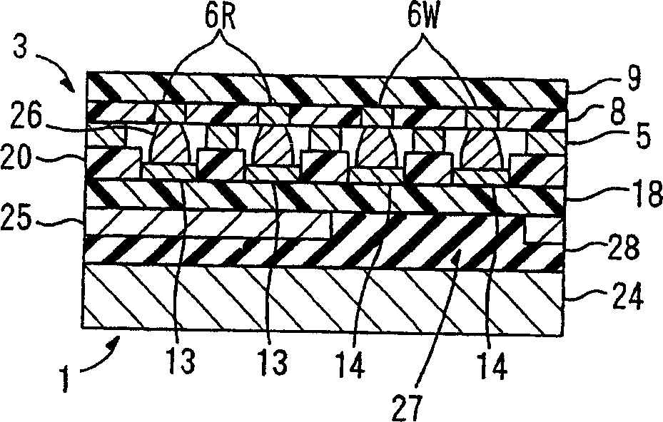
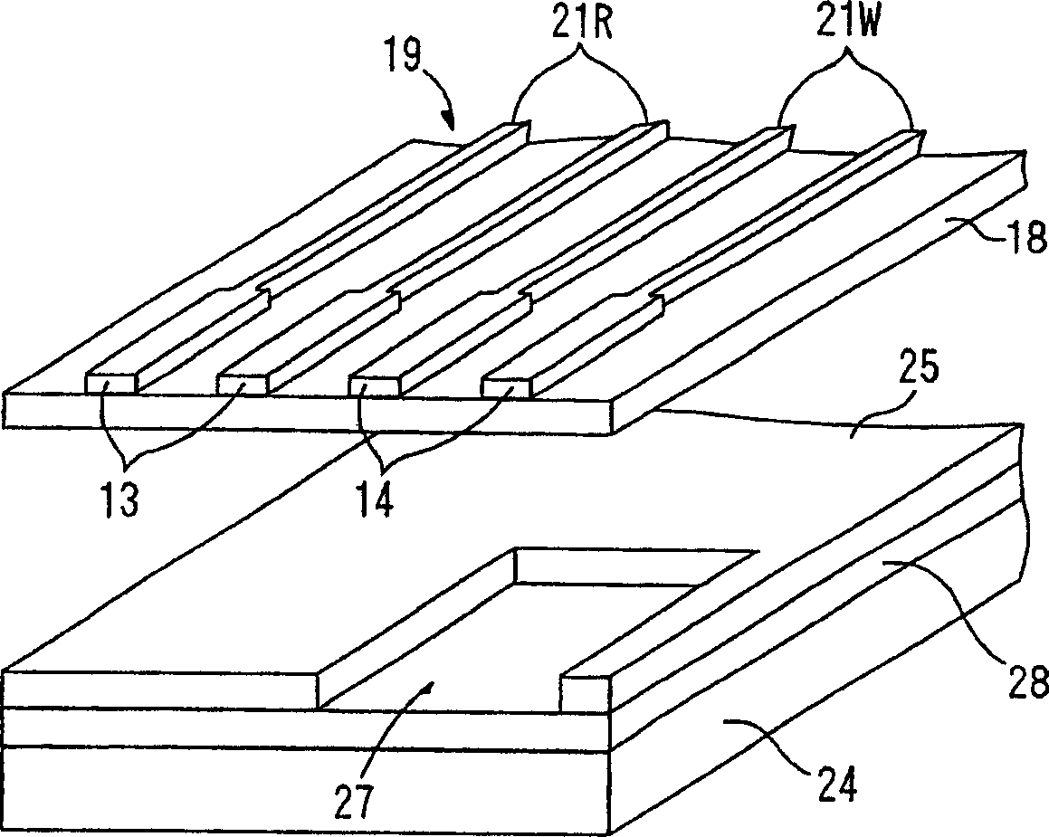
[0075] Then, after etching the copper foil exposed from the resist, the resist is removed, thereby forming a conductive layer having a wiring circuit pattern of a readout line and a write-in line on one side of the polyimide sheet, and the readout The lines and the write lines respectively have a first terminal portion and a second terminal portion, and a conductive plate having an opening hole overlapping each second terminal portion is formed at a part thereof on the...

example 2

[0078] A single-sided copper-clad laminate sheet (ESPANEX (product name) available from Nippon Steel Chemical Co., LTD.) having a 12.5-µm-thick polyimide sheet on one side with a 12.5-µm-thick copper flakes.

[0079] After covering the one-side copper-clad laminated sheet with a dry thin film photoresist, the dry thin film photoresist is exposed to light and then developed to form a resist pattern to cover the wiring circuit pattern forming portion.

[0080] Then, after etching the copper foil exposed from the resist, the resist is removed, thereby forming a conductive layer having a wiring circuit pattern of a readout line and a write-in line on one side of the polyimide sheet. The outgoing and writing lines have first and second terminal portions, respectively.

[0081] Thereafter, a generally rectangular aluminum sheet with a thickness of 100 μm, having an opening hole preformed by punching and having a thickness of 10 μm, is adhesively bonded to polyimide in such a relati...


PUM

PropertyMeasurementUnit
thicknessaaaaaaaaaa
thicknessaaaaaaaaaa
thicknessaaaaaaaaaa

Abstract

A wired circuit board that can control characteristic impedance at connection points between the read wire and write wire of a suspension board with circuit and terminal portions of the wired circuit board connected thereto with a simple structure, to improve signal transmission efficiency for fine pitch wiring or for high frequency signal. A conductive board 25 is adhesively bonded to an insulating base layer 18 of the wired circuit board 1 at one side thereof opposite to the other side on which a suspension-board-side connection terminal portion 11 having a first terminal portion 13 to connect with a read wire 6R of a suspension board with circuit 3 and a second terminal portion 14 to connect with a write wire 6W of the suspension board with circuit 3 is formed, in such a relation that an opening 27 can correspond in position to either of the first terminal portion 13 and the second terminal portion 14, and a stiffener board 24 is adhesively bonded to the conductive board 25 via an adhesive layer 28.

Description

technical field [0001] The present invention relates to a wiring circuit board connected to a support board equipped with a headband circuit of a hard disk drive. Background technique [0002] In a hard disk drive, a support plate equipped with a magnetic head strip has read and write lines for transmitting read and write signals to the magnetic head. The read lines and write lines are connected to a terminal portion of a wiring circuit board equipped with electronic devices such as preamplifier ICs (Integrated Circuits). The read signal from the read line and the write signal from the input line are amplified by electronic devices such as a preamplifier IC provided on the wiring circuit board, and then transmitted from the wiring circuit board to the control circuit board to control the magnetic head. [0003] At the same time, with the improvement of fine-pitch wiring and high-frequency signals in recent years, it is becoming increasingly necessary to control the readout ...

Claims


Application Information

Patent Timeline
Patent Type & Authority Applications(China)
IPC IPC(8): H05K1/02G11B5/48H05K1/05H05K1/14H05K3/00H05K3/36
CPCH05K2201/0969H05K1/056H05K3/363H05K3/0058H05K2201/0715H05K1/0237G11B5/486H05K2201/093H05K2201/0367
Inventor 若木秀一大川忠男大胁泰人
Owner NITTO DENKO CORP
Learn More