Cathode ray tube

A cathode ray tube and connection technology, applied in the field of cathode ray tubes, can solve the problem that the anti-impact performance and anti-squeaking characteristics of the shadow mask 208 cannot be fundamentally improved, etc.

Inactive Publication Date: 2005-02-02
LG PHILIPS DISPLAY KOREA CO LTD
View PDF0 Cites 0 Cited by
  • Summary
  • Abstract
  • Description
  • Claims
  • Application Information

AI Technical Summary

Problems solved by technology

However, in this case, the impact resistance and the anti-squeak ...

Method used


Image

  • Cathode ray tube
  • Cathode ray tube
  • Cathode ray tube

Examples


Embodiment Construction

[0036] Now, preferred embodiments according to the present invention will be described in detail, and examples will be illustrated in the accompanying drawings.

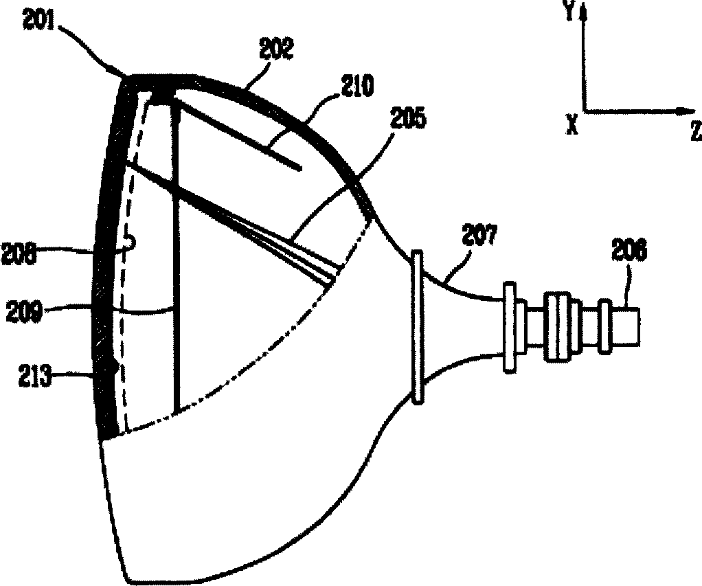
[0037] as in Figure 4 As shown in, a cathode ray tube (CRT) includes: a panel 10 made of front glass whose outer surface is substantially flat and whose inner surface has a predetermined curvature; a funnel-shaped device 20 engaged with the panel 10 and made of rear glass, For forming a vacuum space; a fluorescent screen 130 placed on the inner surface of the panel 10, and used to emit fluorescent light; an electron gun 60 for emitting electron beams 50 that make the fluorescent screen 130 emit light; one installed in a funnel-shaped device The deflection coil 70 on the peripheral surface of 20 and has predetermined interval therewith, is used for deflecting the electron beam 50 on the fluorescent screen 130; One is installed on the shadow mask plate 80 that has fixed interval with the fluorescent screen 130; One is...


PUM


Abstract

A cathode ray tube comprising a panel of which an outer surface is substantially flat; a shadow mask installed with a certain interval from an inner surface of the panel, having a plurality of apertures through which electron beams pass, and formed as a pin-cushion shape in which long and short sides of the shadow mask are inwardly concaved; and the mask frame for fixing and supporting the shadow mask, wherein long and short sides of the mask frame are slanted from ends toward centers thereof in order to maintain a predetermined interval with the long and short sides of the shadow mask. According to this, a strength of the shadow mask is increased and an influence of a magnetic field is reduced thus to obtain an optimum quality.

Description

technical field [0001] The present invention relates to cathode ray tubes, and more particularly to cathode ray tubes capable of improved performance by optimizing the shape of the shadow mask and the shadow mask frame. Background technique [0002] A cathode ray tube is a device that converts electrical signals into electron beams and emits the electron beams to a fluorescent screen to generate images. Cathode ray tubes are widely used in conventional technology due to the ability to obtain good display quality at an affordable price. [0003] Now, a cathode ray tube will be explained with reference to the drawings. figure 1 is a schematic diagram illustrating an example of a conventional art cathode ray tube. Such as figure 1 As shown in , the cathode ray tube includes: a panel 201 made of front glass; a funnel-shaped device 202 made of rear glass engaged with the panel 201 for forming a vacuum space; a fluorescent screen 213, which is placed on the panel 201 and used ...

Claims


Application Information

Patent Timeline
IPC IPC(8): H01J29/07H01J29/80
CPCH01J2229/0727H01J29/073H01J2229/0722H01J29/07
Inventor 崔澳勇
Owner LG PHILIPS DISPLAY KOREA CO LTD
Why Eureka
Try Eureka