

Induction heating cooking device
A technology of induction heating and induction heating coils, applied in induction heating, induction heating control, induction heating devices, etc., can solve the problems of inability to diversify the color or tone of the top plate, and achieve the effect of stable detection characteristics
- Summary
- Abstract
- Description
- Claims
- Application Information
AI Technical Summary
Problems solved by technology
Method used
Image

Examples
Embodiment 1
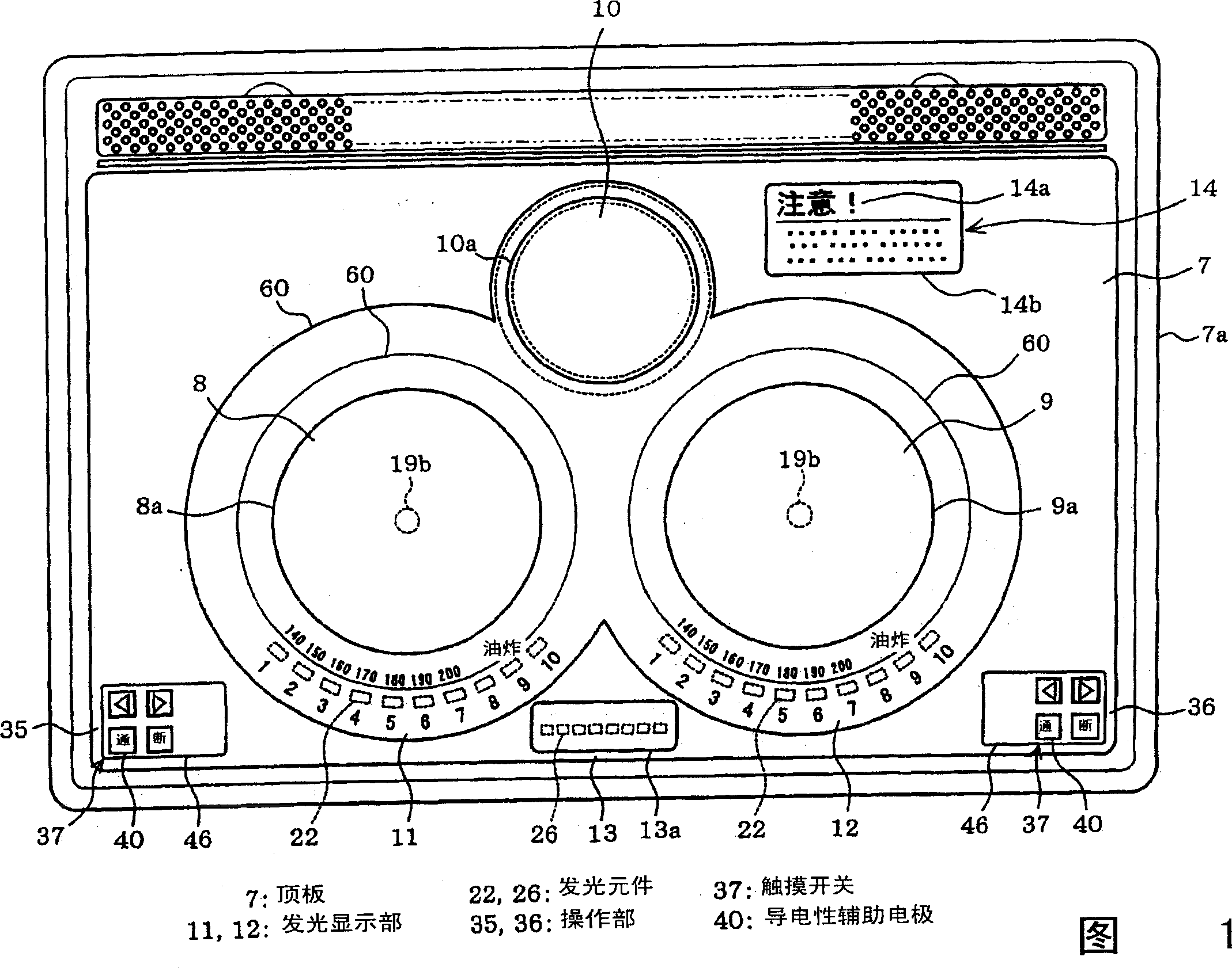
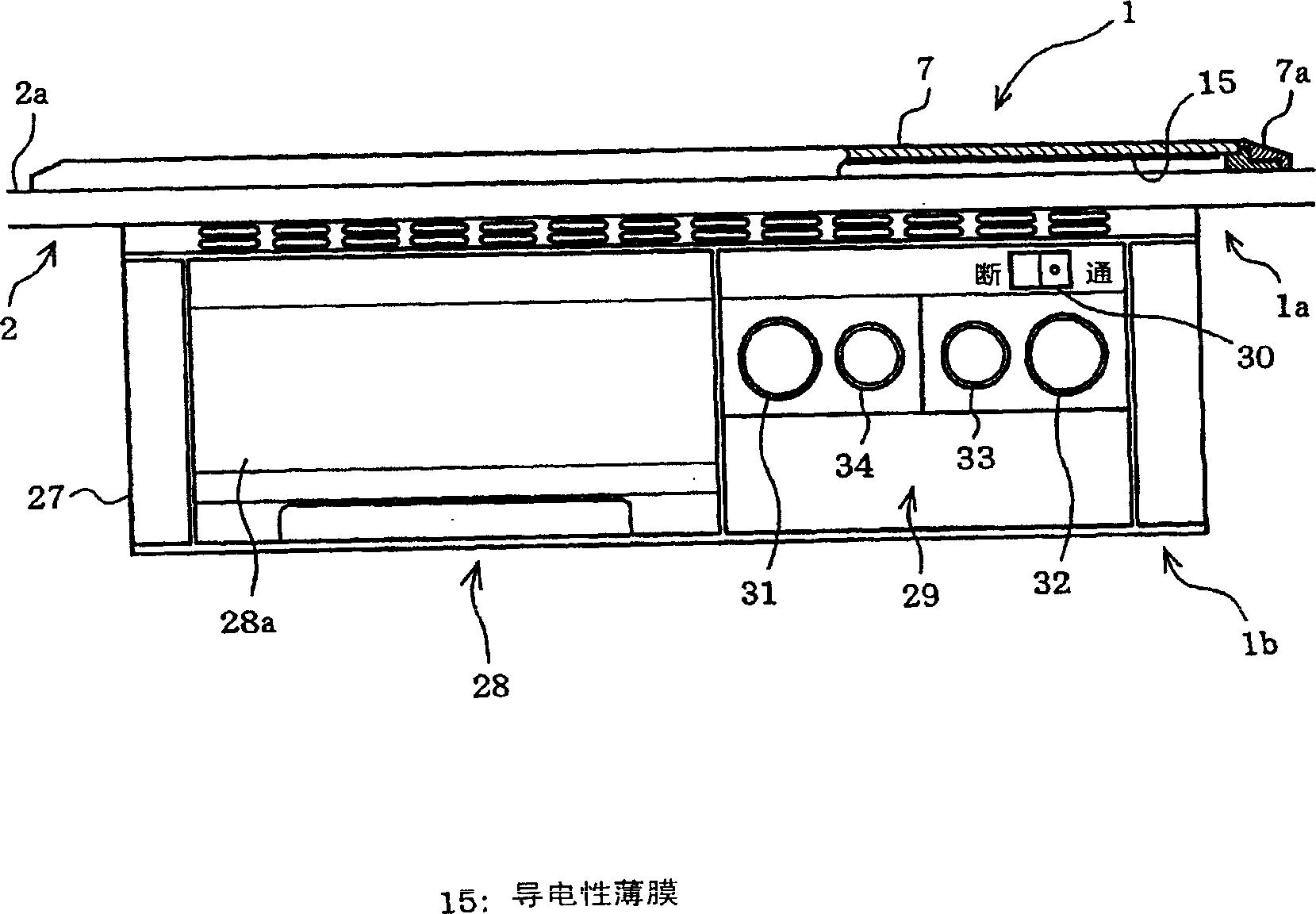
[0034] 1 to 5 show a first embodiment of the present invention. Figure 1 and figure 2 Shown is the whole structure of the heating cooker related to this embodiment. Figure 1 and figure 2 Among them, the heating cooker main body 1 is composed of an upper unit 1a fitted into the cooking table 2 from above and a lower unit 1b located below the upper unit 1a and fitted in from the front of the cooking table 2 .
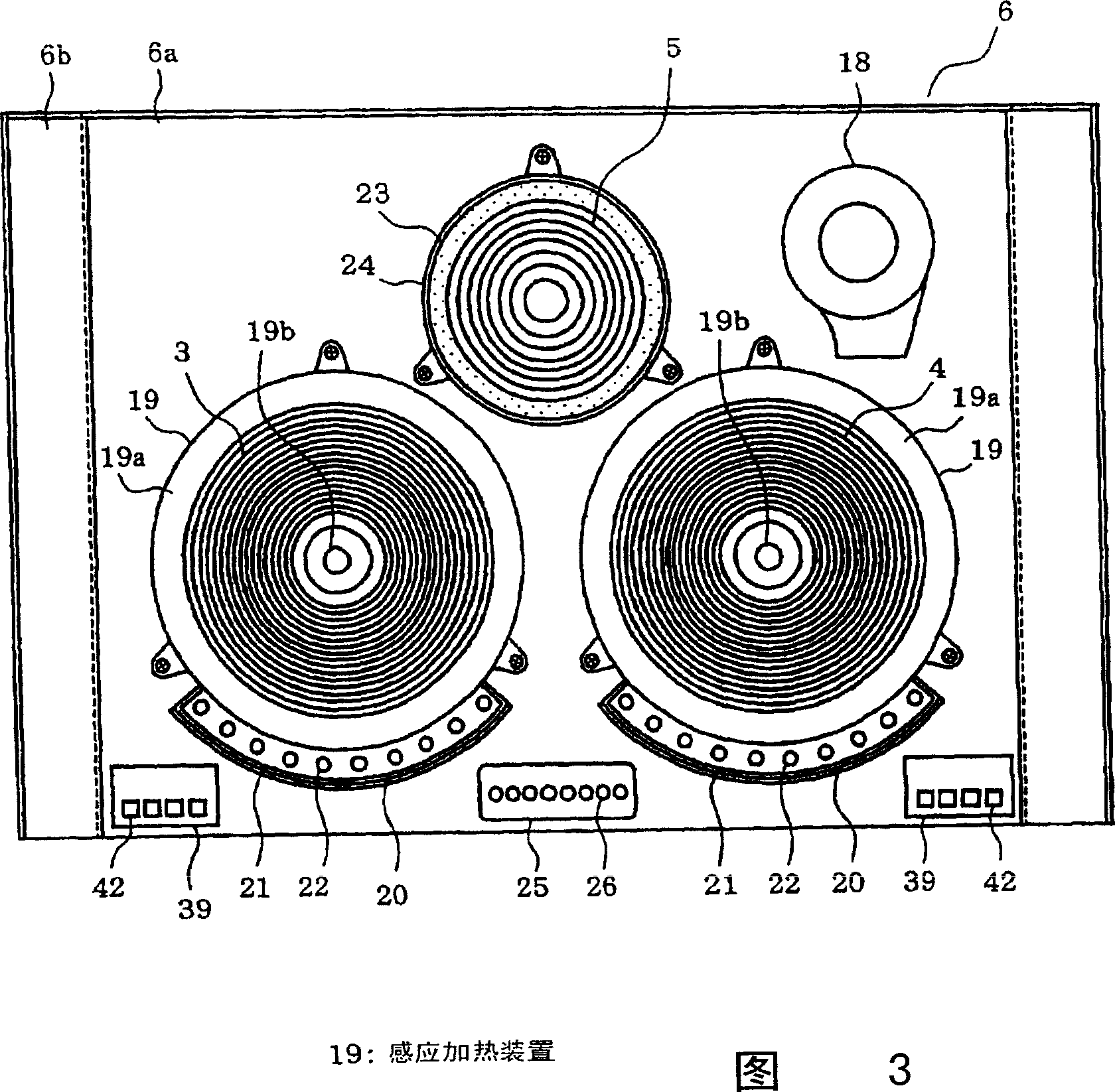
[0035] The upper unit 1a is composed of a casing 6 (see FIG. 3 for both) in which induction heating coils 3 and 4 and a radiation heater 5 are installed as heating means, and a top plate 7 covering an upper surface opening of the casing 6 . The top plate 7 is supported by the outer frame 7a, and is provided on the box body 6 in such a state.
[0036] On the front portion of the upper surface of the top plate 7 , induction heating parts 8 , 9 are arranged side by side corresponding to the induction heating coils 3 , 4 . In the rear center of the top plate 7 , an electr...
Embodiment 2
[0070] Figure 6 and Figure 7 The second embodiment of the present invention is shown, and differences from the first embodiment will be described below. The same reference numerals are assigned to the same parts as those in the first embodiment.
[0071] In this embodiment, the LED 61 as a light source is disposed below the contact portion 40 in the mounting portion 6 a, and a light-transmitting unit 62 for transmitting the light emitted by the LED 61 is provided on the contact portion 40 . The light-transmitting unit 62 is formed by not printing conductive paint on this part, and is formed in the shape of characters and symbols (for example, "on", "off", and arrows) indicating the functions of the touch switch 37 . Therefore, in this embodiment, the contact portion 40 has the functions of a touch switch display film and a conductive auxiliary electrode.
[0072] Since the LED 61 is disposed below the contact portion 40 , the contact portion 40 is disposed closer to the m...
Embodiment 3
[0076] Figure 8 The third embodiment of the present invention is shown, and differences from the second embodiment will be described below. In this embodiment, a cooking time setting switch 71 with a time setting function, such as a cooking time setting switch 71 , is provided on the touch sensing operation unit 35 , and a time display unit 72 is provided behind the switch operation unit 35 . Moreover, although not shown in figure, the touch-sensitive operation means 36 is comprised similarly. In addition, in this embodiment, the top plate used is not a wide top plate, but has a size substantially equal to the width of the mounting portion 6a.
[0077] The cooking time setting switch 71 is the same as the touch switch 37 shown in the second embodiment, and is composed of a contact portion 40, touch detection electrodes (not shown), LEDs (not shown), and the like. Furthermore, a light transmission unit 62 for transmitting light from the LED is provided on the contact portion...
PUM
 Abstract
Description
Claims
Application Information