
Electric connector

A technology of electrical connectors and contactors, applied in the direction of connection, fixed connection, circuit, etc., can solve the problems of inability to realize electrical connection, poor contact, etc., and achieve the effects of preventing peeling, good friction, and realizing design and production

Inactive Publication Date: 2005-02-16
JST MFG CO LTD
View PDF0 Cites 5 Cited by
  • Summary
  • Abstract
  • Description
  • Claims
  • Application Information

AI Technical Summary

Problems solved by technology

[0006] However, dust, etc. may adhere to the terminal surface of the battery, or an oxide film may be formed. If there is an oxide film, etc., poor contact occurs and good electrical connection cannot be achieved.

Method used


Image

  • Electric connector
  • Electric connector
  • Electric connector

Examples


no. 1 Embodiment

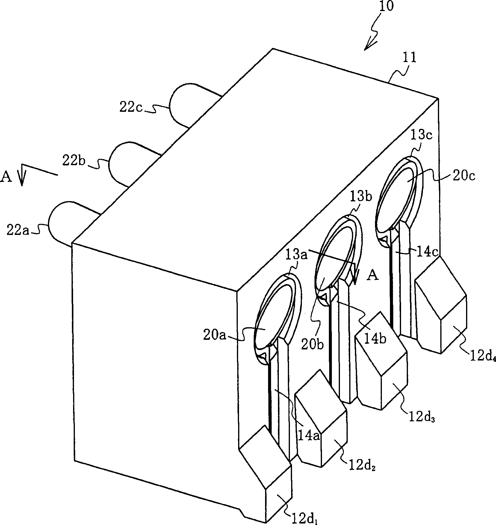
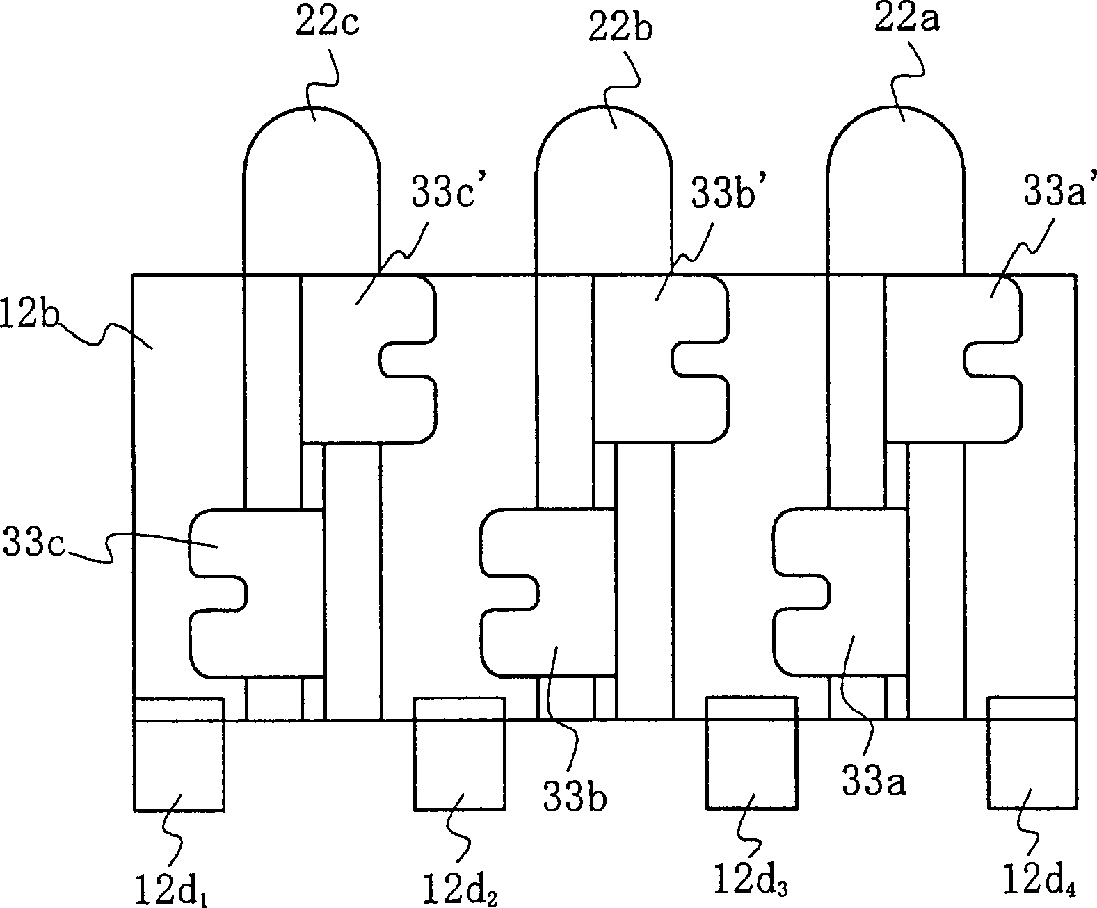
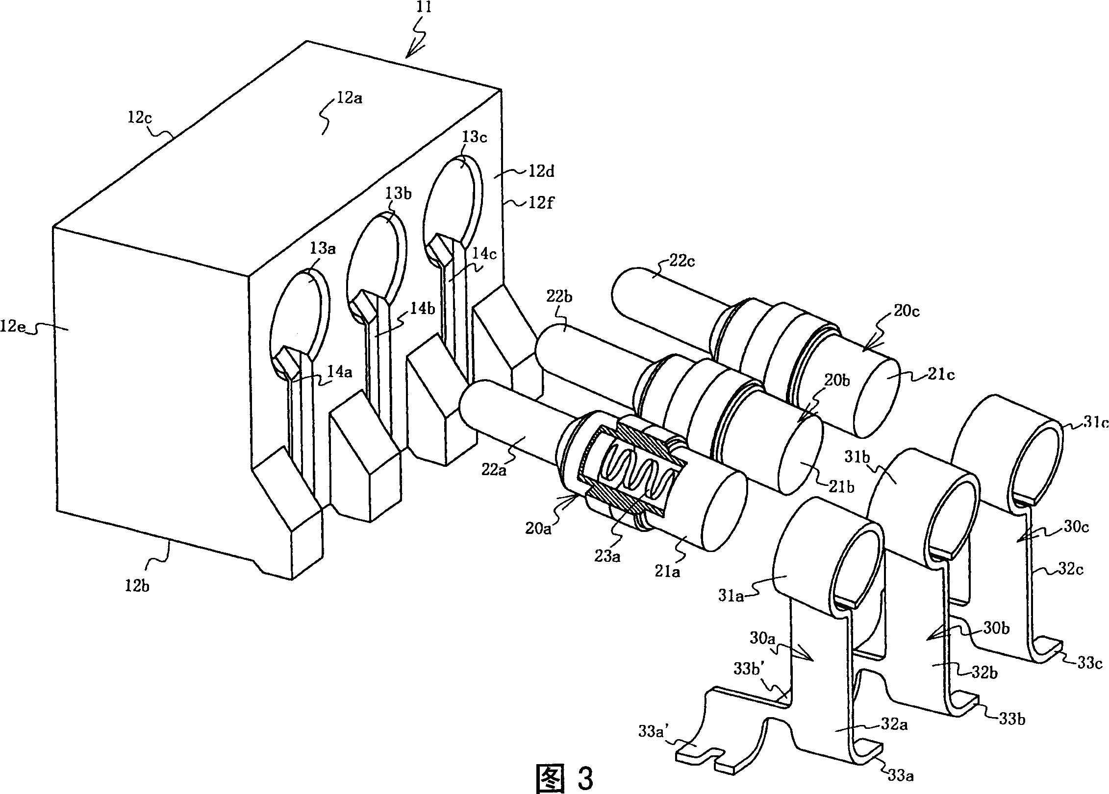
[0034] figure 1 It is a perspective view showing the appearance of the electrical connector of the present invention, figure 2 is the bottom view of the electrical connector, Figure 3 is the figure 1 The exploded perspective view of the electrical connector exploded, Figure 4 along figure 1 The cross-sectional view of the A-A line in Fig. 5 shows the terminal part of Fig. 3, Fig. 5(a) is a left side view, Fig. 5(b) is a front view, Fig. 5(c) is a bottom view, Figure 6 To show the side view of the probe type contactor, Figure 7 It is a side view showing the connection state between the electrical connector and the equipment.

[0035] The electrical connector 10 like figure 1 , shown in FIG. 3 , including a housing 11, the housing 11 has, for example, three through holes 13a-13c; probe-type contactors 20a-20c inserted into each through-hole; terminal parts 30a-20c connected to each probe-type contactor 30c, each of the above-mentioned probe type contacts 20a-20c is ...


PUM


Abstract

An electric connector using a probe-type contact(s) is provided to prevent it from having contact failure and is characterized in that it comprises a housing having at least one through hole, a probe-type contact(s) inserted into the through hole(s), and a terminal portion(s) connected to the probe-type contact(s). In the probe-type contact, a pin-shaped contact(s) is housed in a conductive tubular body in such manner that the contact is energized to move freely by a spring. The tip of the pin-shaped contact is tilted upward at a predetermined angle in a horizontal direction, and is installed into the through hole so as to protrude from the front wall surface of the housing.

Description

technical field [0001] The present invention relates to electrical connectors, and more particularly, the present invention relates to improvements in electrical connectors employing a contactor, a so-called probe-type contactor, which is movable in a front-to-rear direction by spring-biasing a tube The foot contacts are received inside the conductive cylindrical body. Background technique [0002] First, an electrical connector using a conventional probe type connector will be described using the drawings. 8 shows an electrical connector using a probe-type contactor described in Patent Document 1 below. FIG. 8(a) is a sectional view of the contactor, and FIG. [0003] The probe type contactor 2 is constructed in the following manner. As shown in FIG. The front end of the sex tube 4 is provided with a narrow portion, and the conductive pin 3 is not pulled out along the protruding manner. In addition, a coil spring 5 is provided in compression so as to elastically bias the...

Claims


Application Information

Patent Timeline
Patent Type & Authority Applications(China)
IPC IPC(8): H01R13/64H01R12/71H01R13/187H01R13/24
CPCH01R12/57H01R13/2421H01R13/64H01R13/187
Inventor 折原昌幸
Owner JST MFG CO LTD
Learn More