Fuel pomp

A technology of fuel pump and commutator plate, applied in the field of fuel pump, can solve problems such as deposition, and achieve the effects of low production, good cleaning and simple cost

Inactive Publication Date: 2006-12-27
SIEMENS AG
View PDF0 Cites 2 Cited by
  • Summary
  • Abstract
  • Description
  • Claims
  • Application Information

AI Technical Summary

Problems solved by technology

Especially in alcohol-containing fuels, which have the property that they gradually become electrically conductive, the disadvantage here is that corrosion products are deposited on the sliding surfaces of these carbon brushes by electrochemical processes

Method used


Image

  • Fuel pomp

Examples


Embodiment Construction

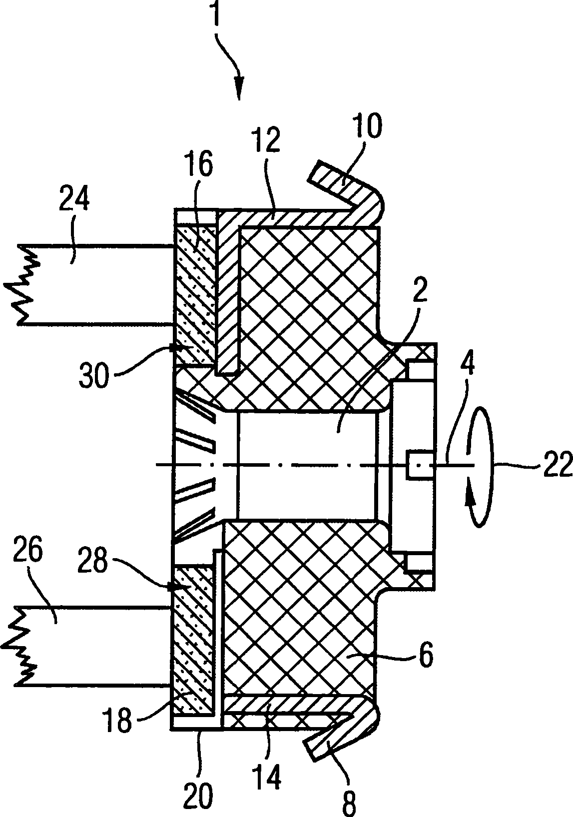
[0016] The figure shows a rotor 1 of a commutator motor (not further shown) of a fuel pump. During fuel pump operation, a rotor 1 with a rotor shaft 2 rotates about a rotor axis 4 and is provided with rotor coils 6 . The ends of the rotor coil 6 are electrically conductively connected to the connection terminals 8 , 10 of the contact pieces 12 , 14 .

[0017] Furthermore, the commutator segments 16 , 18 of a graphite, preferably composed of graphite, coaxially arranged on the rotor shaft 2 are connected to the commutator segments 16 , 18 with the contact segments 12 , 14 . The segments 16 , 18 are thus electrically connected to the rotor coil 6 . The segments 16 , 18 of the commutator 20 are oriented radially away from the commutator axis with respect to the commutator axis which coincides with the rotor axis 4 . When the rotor 1 rotates (marked with arrow 22) and thus the commutator 20 rotates, the carbon brushes 24, 26 preloaded by means of spring means (not shown) slide a...


PUM


Abstract

The invention relates to a fuel pump comprising an electromotive drive that has a commutator (20) and carbon brushes (24, 26) that brush alternately against commutator segments (16, 18) when said commutator (20) is rotated. The aim of the invention is to improve the corrosion resistance and to clean the carbon brushes (24, 26). To achieve this, the commutator segments (16, 18) contain graphite and at least one commutator segment (16, 18) contains graphite and an admixture of a material (30) that has a greater hardness than graphite.

Description

technical field [0001] The invention relates to a fuel pump having an electric drive with a commutator and carbon brushes which alternately slide on commutator segments when the commutator rotates. Background technique [0002] Fuel pumps of this type are already known. The fuel pump is used in particular in motor vehicles and is used to deliver fuel from a fuel tank to a carburetor or an injection system of an internal combustion engine. In this case, the electric drive is realized by means of an electric motor with a commutator, a so-called commutator motor. The commutator, also known as the commutator, is a cylindrical part mounted coaxially on the shaft of the commutator motor, consisting of thin copper sheets with insulating spacers forming the commutator segments, and connected to the so-called electric Pivot coil connection. Copper wire mesh brushes or carbon brushes that feed the current slide over the commutator. [0003] A disadvantage of such commutator motors...

Claims


Application Information

Patent Timeline
Patent Type & Authority Applications(China)
IPC IPC(8): F02M37/10H01R39/04
CPCH01R39/045F02M37/10
Inventor 沃尔夫冈·瓦恩克
Owner SIEMENS AG
Why Eureka
Try Eureka