Process for machining ends, positioning ports and holes of central opened pump by special boring apparatus

A process method and end face technology, applied in boring/drilling, metal processing equipment, drilling/drilling equipment, etc., can solve the problem of inflexible operation of rotor parts, poor product quality and quantity, and coaxial holes of each hole. To solve problems such as large accuracy error, to achieve the effect of speeding up the time of product launch, improving product quality, and flexible rotation

Inactive Publication Date: 2005-02-23
SHANGHAI LIANCHENG GRP SUZHOU
View PDF0 Cites 12 Cited by
  • Summary
  • Abstract
  • Description
  • Claims
  • Application Information

AI Technical Summary

Problems solved by technology

In this processing method, since the end face positioning spigot and each hole are processed twice, the coaxiality error of each hole is relatively large, and the error between the hole and the two end faces and the positioning spigot is also large, resulting in the processing of the processed product. , resulting in inflexible operation of the rotor components, immobility of the hand plate, unstable operation of the equipment after starting up, accompanied by serious stagnation, and the continuous rework of the processed products, so that the quality and quantity of the products have not been improved, which has affected the quality of the products. Development progress and product launch time

Method used


Image

  • Process for machining ends, positioning ports and holes of central opened pump by special boring apparatus
  • Process for machining ends, positioning ports and holes of central opened pump by special boring apparatus
  • Process for machining ends, positioning ports and holes of central opened pump by special boring apparatus

Examples


Embodiment 1

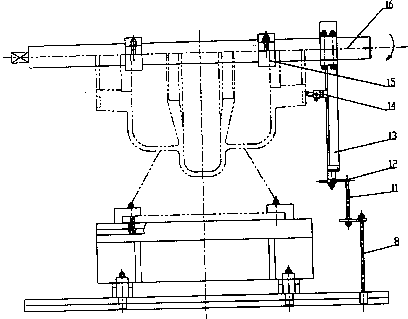
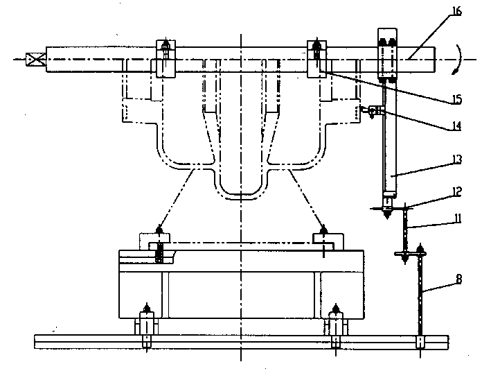
[0012] Example 1: See attached figure 1 The method of opening the end face of the pump and positioning the stop using a special boring machine.

[0013] The support frame of the boring device 15 is fastened to the screw hole on the right side of the open face of the pump body. The power drives the boring bar 16 through the universal joint and drives the knife mechanism to rotate. The dial 12 on the knife mechanism 13 rotates to When it hits the lever 11, turn the dial 1 / 5 circle, and the dial is divided into 5 equal parts, driving the screw on the knife mechanism 13 to rotate 1 / 5 circle, and the screw drives the nut under the tool holder 14 Move 1 / 5 of the pitch forward to complete a tool pass; the tool feed mechanism continuously rotates, and the tool on the tool holder continuously cuts forward to complete the rough and fine processing of the end face of the pump body; the positioning stop is processed in the same way; the tool travel mechanism 13 and the support rod 8, the shi...

Embodiment 2

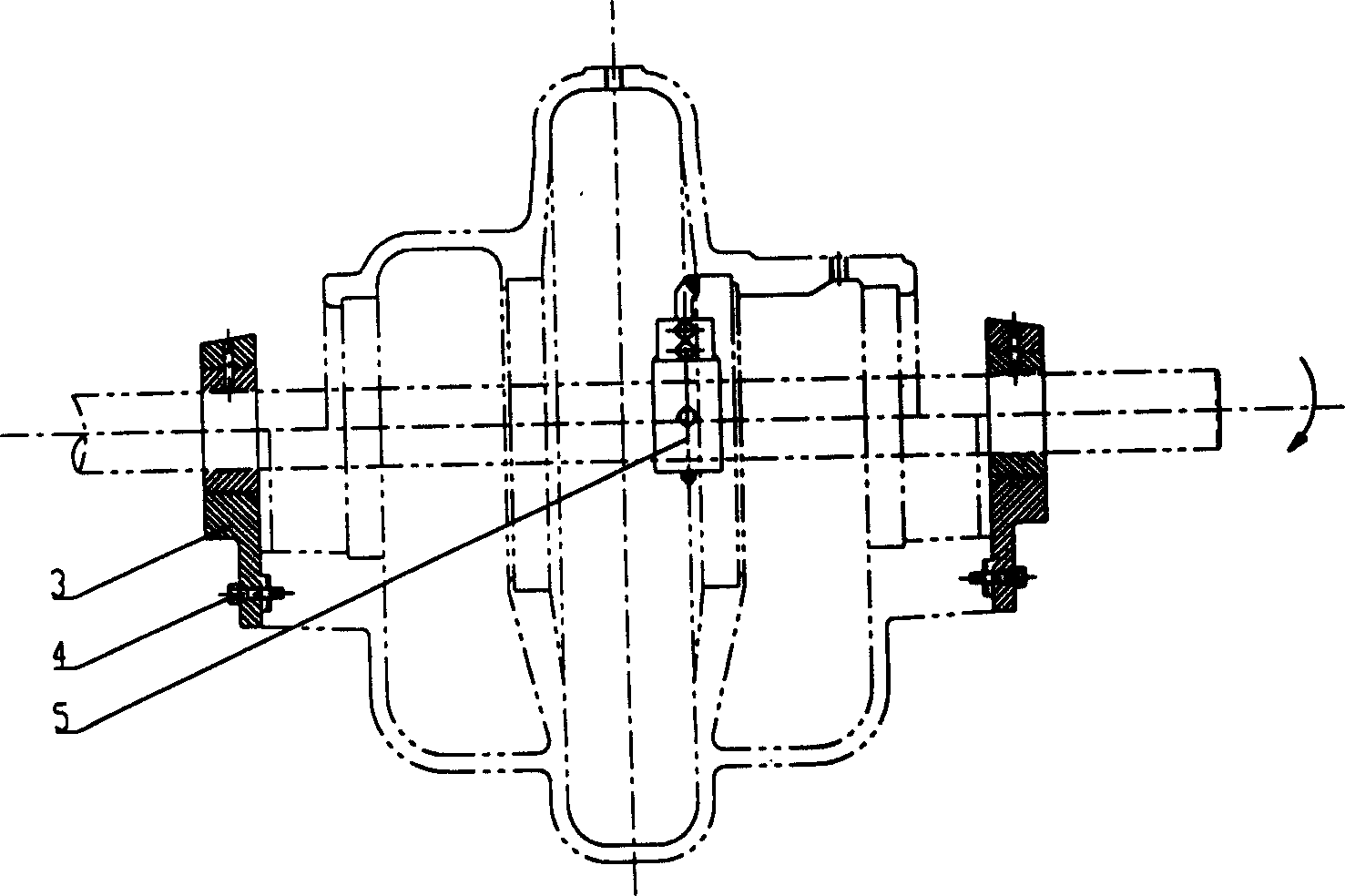
[0014] Example 2: See attached figure 2 , Use boring special machine to process the pump hole system.

[0015] Taking the finished pump body's end faces and positioning stop as the reference, the bearing body 3 is fastened to the corresponding end face and positioning stop of the pump body with bolts 4; when the boring bar rotates, the boring tool holder 5 fixed on the boring bar is driven Rotate, the tool on the boring tool holder 5 cuts the holes on the pump body and pump cover until all the holes are processed. When measuring the hole diameter of the pump body and pump cover, open the pump cover and close the pump cover with positioning pins after the measurement is completed. After the positioning pins are tightened, tighten them and continue processing until the requirements are met . The boring tool holder 5 can be used to boring the hole system on the pump body and the pump cover. The jump of the two end faces of the pump body and the positioning stop is less than 0.05.


PUM


Abstract

A technology for machining the end face, locating stop and holes of centrally splitting pump by special boring machine includes such steps as fixing the boring unit to the screwed hole on the centrally splitted surface of pump body, driving boring rod while rotating feeding gear, rotating the dial, turning the dial by 1/5 of a turn by a turning rod, turning the leading screw by 1/5 of a turn, and driving the nut under tool carrier to advance by 1/5 of a pitch to complete a feeding. Said locating stop is machined in same way. Said holes are machined by using said end face and locating stop as reference.

Description

Technical field [0001] The invention belongs to a machining process method, and particularly relates to a process method for processing the end face, positioning stop and hole system of a middle pump with a special boring machine. Background technique [0002] In the prior art, the end face of the split pump, the positioning stop and the hole system are all processed on a general-purpose machine tool T68 horizontal boring. The processing technique is to first process one end surface, positioning stop, sealing body hole, and sealing ring hole; then turn the worktable 180 degrees to round the processed hole, and then process the other end surface, positioning stop and hole. This processing method, because the end face positioning stop and each hole are processed in two times, the coaxiality error of each hole is relatively large, and the error between the hole and the two end faces and positioning stop is also large, resulting in the processed product in the final assembly. , Resul...

Claims


Application Information

Patent Timeline
Patent Type & Authority Applications(China)
IPC IPC(8): B23B35/00B23B41/00
Inventor 谢张国卢永滨周绪安
Owner SHANGHAI LIANCHENG GRP SUZHOU
Why Eureka
Try Eureka