

Hydraulic tripper of strong rammer and its tripping method
A technology of dynamic compaction machine and decoupling device, which is applied in soil protection, load hanging components, construction, etc., can solve problems such as danger, wear of hook mouth, poor working conditions, etc., and achieves low impact, low wear, and decoupling. Quick and thorough effect
- Summary
- Abstract
- Description
- Claims
- Application Information
AI Technical Summary
Problems solved by technology
Method used
Image

Examples
Embodiment Construction
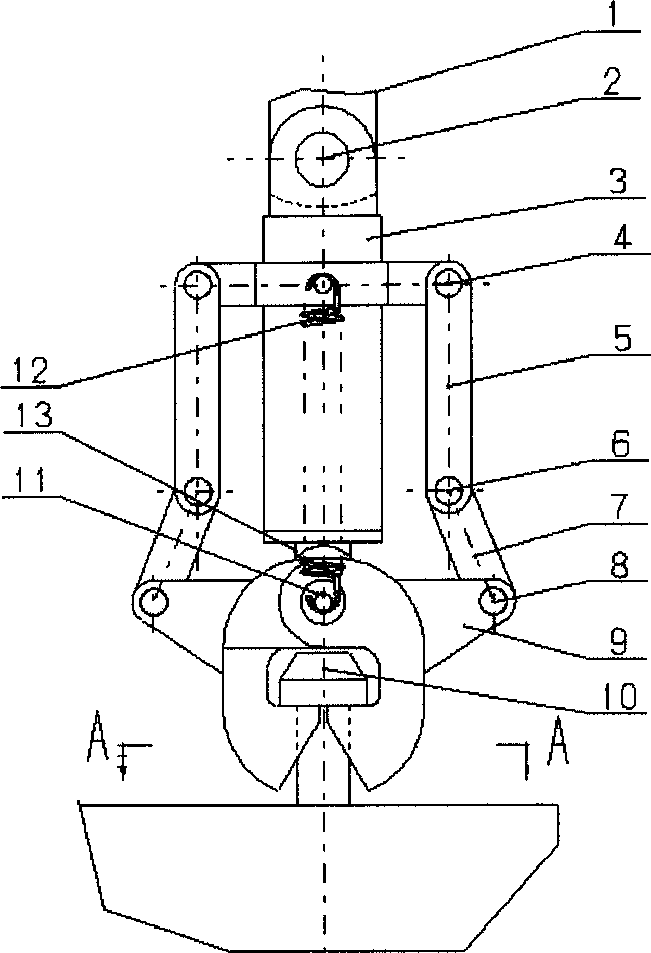
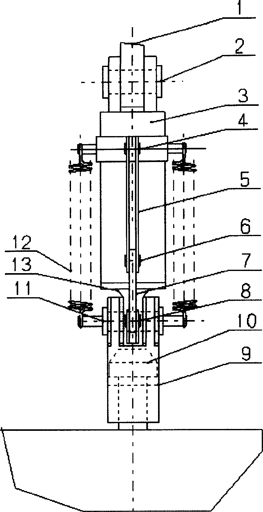
[0019] The hydraulic uncoupling device for the rammer of the dynamic compaction machine is composed of a mechanical device and a hydraulic control system, of which:
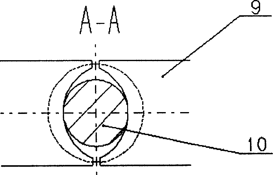
[0020] a. The mechanical device is composed of hydraulic cylinder 3, connecting rods 5 and 7, lifting lug 9 and spring 12. Oil cylinder 3 and upper connecting rod 5 are connected by hinge shaft 4, and upper connecting rod 5 and lower connecting rod 7 are connected by hinge shaft 6. , The lower connecting rod 7 is connected with the lifting lug 9 through the hinge shaft 8, and the lifting lug 9 is connected with the piston rod 13 through the pin shaft 11, and each component is rotatable relative to the connecting shaft. The piston rod 13 is connected to the cylinder body of the oil cylinder 3 through the spring 12; the hook between the tamper 10 and the decoupler is realized through the groove between the two lifting ears 9 and the head of the tamper 10 with the flange.
[0021] b. The hydraulic control system con...
PUM
 Abstract
Description
Claims
Application Information