Pressure power machine

A press machine and motive technology, applied in the direction of machines/engines, mechanisms for generating mechanical power, mechanical equipment, etc., can solve problems such as power and energy consumption, achieve fast running speed, ensure continuity, and operate safely

Inactive Publication Date: 2005-03-02
李新刚
View PDF0 Cites 1 Cited by
  • Summary
  • Abstract
  • Description
  • Claims
  • Application Information

AI Technical Summary

Problems solved by technology

[0003] The purpose of the present invention is to solve the disadvantages of power and energy consumption in existing vehicles, ships and power generati

Method used


Image

  • Pressure power machine

Examples


Embodiment Construction

[0047] The following is a further description of the dual structure features and working principle of the compressor in combination with the accompanying drawings:

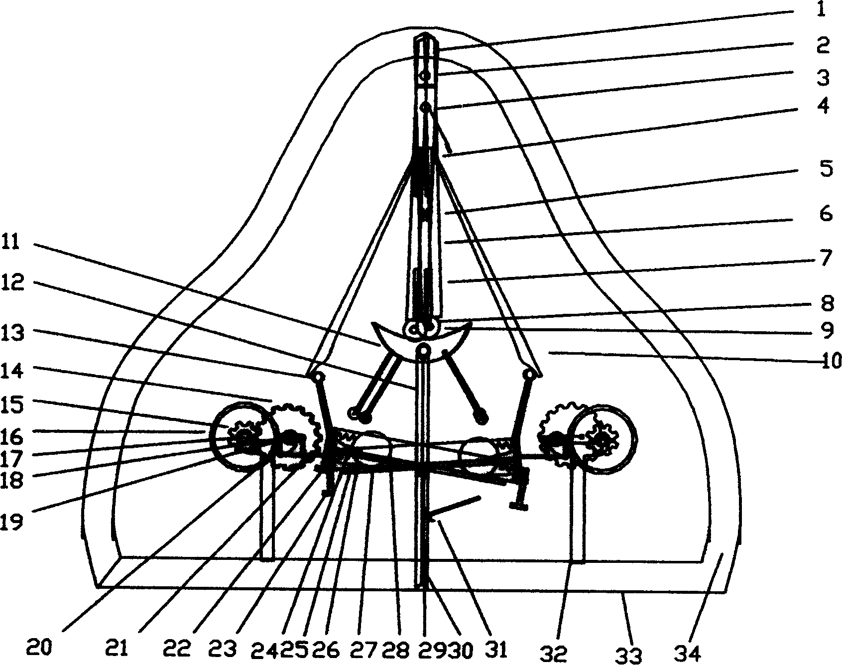
[0048] The present invention uses the principle of the earth's rotation to design a self-propelled press machine with air as the raw material. The press machine is composed of two parts and a hard steel device. The mutual connection of self-pushing and self-rotation is established on the double-structure device, and the double-structure is set. The device runs in reverse around the fixed point, and the joint force of the two parties can transform the fixed pressure of the high-pressure rod 1 into eternal power.

[0049] Two vertical cylindrical high-pressure rods (power source) are installed on the top of the press. The upper part of the high-pressure rod 1 is equipped with a rod top shaft 2, the lower part is equipped with a rod bottom roller 9, and the middle part is equipped with a pressure regulating rod 3 and ...


PUM


Abstract

The invention relates to a kind of double-structure, multi-functional pressing engine, including high-pressure bar, pressure-adjusting pole, pressure-exchanging pole, prying pole, semimonthly fork, the big rack, spring piece, spring hook, connecting rod, gyro wheel, hanging tracks, hanging wheel, main shaft, round shaft, support, brakes, and so on. On the component that consists of double-structure set up the connection of self-anti-elastic, self-pushing and self-rotating. That can develop the energy-supporting functions, such as generating electricity, transporting, and the effective energy-saving efficiency.

Description

technical field [0001] The invention relates to a pressing machine, more specifically a self-pushing and self-rotating pressing machine. Background technique [0002] In the current existing technology, vehicles, ships, airplanes and other means of transportation, as well as devices such as water turbines and generators, all rely on the outside world to provide power and energy, which not only consumes a lot of energy, but also causes exhaust gas pollution and increases urban noise. Contents of the invention [0003] The purpose of the present invention is to provide an energy self-sufficient compressor for the disadvantages of power and energy consumption in existing vehicles, ships and power generating devices. The compressor can convert its own pressure into eternal power and output energy for a long time. [0004] The pressing machine described in the present invention is a double-structure pressing machine, including high-pressure rods, pressure changing rods, prying ...

Claims


Application Information

Patent Timeline
IPC IPC(8): F03G7/10
Inventor 李新刚
Owner 李新刚
Why Eureka
Try Eureka