Ice smelting and cold storage device in parallel mono heat exchanger

A cold storage device and heat exchanger technology, applied in the direction of indirect heat exchangers, heat exchanger types, heating methods, etc., can solve the problem of increasing the complexity of the system pipeline, reducing the stability of the control system, and the difficulty of controlling the cold storage system and other issues to achieve the effect of saving initial investment, reducing possibility, and reducing energy consumption

Inactive Publication Date: 2005-03-02
TSINGHUA UNIV
View PDF0 Cites 18 Cited by
  • Summary
  • Abstract
  • Description
  • Claims
  • Application Information

AI Technical Summary

Problems solved by technology

The system of the parallel double heat exchanger system adopts the structure of separating the cold loop of the ice tank and the refrigeration loop of the chiller. Although the control of the cold storage system becomes relatively simple and clear, it greatly increases the complexity of the system pipeline. and the initial investment of the system, so it is rarely used in actual engineering
Because the parallel single heat exchanger system adopts the structure of double pumps in series, when the unit operates in different modes, the resistance object responsible for each pump changes, which makes it very difficult to control the cold storage system and reduces the stability of the control system. At the same time, if the resistance of the system varies greatly under different modes, a variable speed pump is required, which increases the initial investment of the system
Based on this, the existing parallel single heat exchanger system is rarely used in practice

Method used


Image

  • Ice smelting and cold storage device in parallel mono heat exchanger
  • Ice smelting and cold storage device in parallel mono heat exchanger
  • Ice smelting and cold storage device in parallel mono heat exchanger

Examples


Embodiment Construction

[0026] The present invention will be further described below in conjunction with the accompanying drawings and specific embodiments.

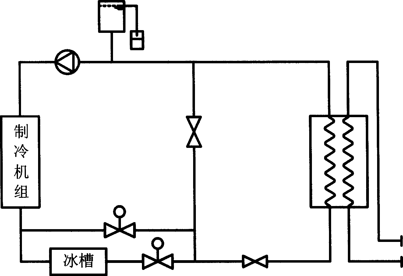
[0027] Figure 5 It is a structural schematic diagram of an embodiment of an ice-melting and cold storage device in a parallel single heat exchanger provided by the present invention.

[0028] The device is composed of a refrigeration unit 1, an ice tank 2, a heat exchanger 3, a brine pump 4, and corresponding brine pipelines and regulating valves. The refrigerating unit 1 and the heat exchanger 3 are connected by pipelines to form a loop, and the heat exchanger regulating valve 8, the brine pump 4 and the refrigerating machine regulating valve 7 are sequentially arranged on the pipeline between the outlet of the heat exchanger 3 and the inlet of the refrigerating unit 1; The ice tank pipeline is connected to the pipeline between the brine pump 4 and the refrigerator regulating valve 7, the ice tank regulating valve 6 and the ice tank 2 are ar...


PUM


Abstract

The invention discloses a parallel heat exchanger melting ice cold accumulation device, comprising refrigerating unit and heat exchanger connected as a loop and heat exchanger adjusting valve, secondary refrigerant and refrigerator adjusting valve set on the pipelines of heat exchanger outlet and refrigerating unit inlet; an ice tank pipeline connected to the pipeline between secondary refrigerant pump and refrigerator adjusting valve, with ice tank adjusting valve and ice tank set orderly on it, and its another end connected to the pipeline between refrigerating unit outlet and exchanger melting inlet; bypass line connected to the pipeline between heat exchanger adjusting valve and secondary refrigerant pump, with a bypass adjusting valve set on it and another end connected to the pipeline between ice tank adjusting valve and ice tank. The device which maintains the advantages of original parallel heat exchanger system can realize five operating modes of cold accumulation, ice tank supplying ice, refrigerator supplying refrigeration, ice tank and refrigerator unifying supplying refrigeration and simultaneous accumulating and supplying, meanwhile has simplified control method of parallel heat exchanger system, increased its stability and decreased its cost.

Description

technical field [0001] The invention belongs to the technical field of refrigeration and air conditioning and ice storage, and in particular relates to a structural design of an ice-melting storage device in a parallel single heat exchanger. Background technique [0002] The ice-storage air-conditioning system uses cheap power during the low-load period of the power grid, such as night power, to store the cold energy produced by the refrigeration system in water through a refrigerant (usually ethylene glycol aqueous solution), and freeze the water into ice; During the high-load period of the power grid with expensive electricity prices, such as daytime, the cold energy in the ice is released to supply cooling to the air-conditioning system, thereby reducing the demand for electricity during the high-load period of the power grid, and realizing the air-conditioning system of "shifting peaks and filling valleys" of the power system. In areas with tight power supply, the ice st...

Claims


Application Information

Patent Timeline
Patent Type & Authority Applications(China)
IPC IPC(8): F24F5/00F28D20/02
CPCY02E60/147Y02E60/145Y02E60/14
Inventor 王宝龙石文星李先庭余延顺李寒春
Owner TSINGHUA UNIV
Why Eureka
Try Eureka