Accurately positioning method and device for underground layered power cable defect position

A technology for precise positioning of power cables, applied in the field of power cables, to achieve the effects of simple installation, avoidance of interference, and convenient use

Inactive Publication Date: 2005-03-02
杨军
View PDF0 Cites 23 Cited by
  • Summary
  • Abstract
  • Description
  • Claims
  • Application Information

AI Technical Summary

Problems solved by technology

[0017] The purpose of the present invention is to solve the defects existing in the existing power cable fault detection technology and propose a method and device for accurately locating the fault location of underground power cables

Method used


Image

  • Accurately positioning method and device for underground layered power cable defect position
  • Accurately positioning method and device for underground layered power cable defect position
  • Accurately positioning method and device for underground layered power cable defect position

Examples


Embodiment

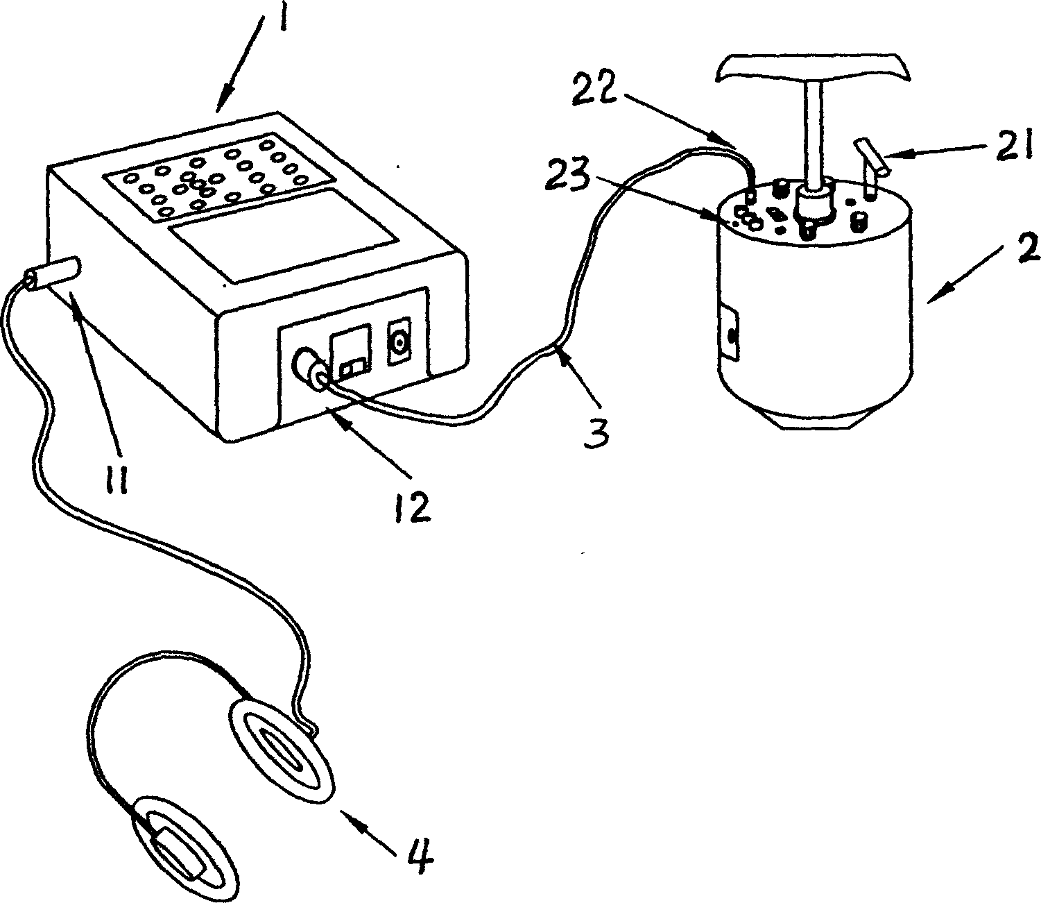
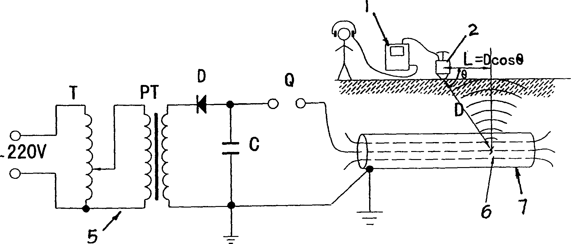
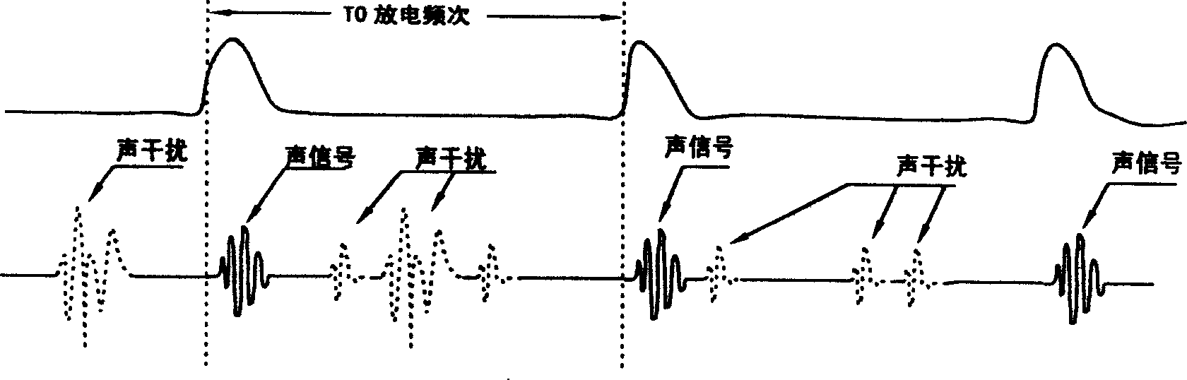
[0082] After completing the distance-to-fault range measurement, press the figure 2 Connect the high voltage pulse generator. Connect the output terminal of the high-voltage pulse generator to the faulty phase of the cable under test, and connect the outsourced high-voltage ground of the cable to the ground wire of the high-voltage pulse generator and then to the ground. By adjusting the pulse voltage level, control the pulse discharge frequency to apply to the faulty phase of the cable within 3-5 seconds. discharge pulse.

[0083] Within the cable fault distance range, according to the cable laying conditions, take two points A and B along the cable path, and measure the distance L between the two points. See Figure 7

[0084] Connect the magnetic-acoustic receiver to the data processing display through a special cable, and plug the earphones into the data processing display or the headphone output socket of the magnetic-acoustic receiver.

[0085] Turn on the power swi...


PUM


Abstract

The invention relates to a failure localizing method and device for underground electric cable, which includes time domain filter method and two-point difference speed trial method and the device for realizing above mentioned method. The time domain filter method includes failure point pulse discharging frequency; electromagnetic reception and sound wave reception; and the synchronous action of above three aspects; and sets the time period for closing discharging frequency. The two-point difference speed trial method places the magnetic detector as A and B points, samples and stores time data Ta and Tb at the two points; and works out the distance form the failure point to the measuring point through formula. The device includes electromagnetic amplification and comparison outputting circuit of received magnetic signal, the output circuit inputs the starting igniting pulse generated by the magnetic signal to the control pulse generating circuit, the pulse generating circuit generates magnetic wave through the potentiometer and closes the adjustable pulse width T1, and starts the adjustable pulse T2 of sound channel synchronous to it.

Description

technical field [0001] The invention relates to a power cable laid underground, and mainly refers to a method and a device for accurately locating the fault location of an underground power cable for detecting and determining the location of the fault point when the cable fails. Background technique [0002] The power cable fault detection system is mainly composed of three parts: cable fault distance measurement equipment (hereinafter referred to as: equipment A); cable fault location positioning equipment (hereinafter referred to as: equipment B); cable buried path measurement equipment (hereinafter referred to as: equipment C ). [0003] The main measurement principle adopts pulse echo method (commonly known as radar ranging), magnetic and acoustic positioning method, high voltage and high current sampling, etc. [0004] The specific technology covers: microelectronics technology fields such as microwave, analog, digital, and single-chip microcomputer programming. [00...

Claims


Application Information

Patent Timeline
Patent Type & Authority Applications(China)
IPC IPC(8): G01R31/08G01R31/11G01V3/11
Inventor 杨军
Owner 杨军
Why Eureka
Try Eureka