Two path 2X2 light switch and 4X4 free space light switch composed of it

An optical switch and light polarization technology, applied in optics, optical components, instruments, etc., can solve the problems of difficult optical debugging, many optical components, complex structure, etc., and achieve the effect of compact structure of optical switch and few optical components

Inactive Publication Date: 2005-03-02
HUAZHONG UNIV OF SCI & TECH
View PDF0 Cites 3 Cited by
  • Summary
  • Abstract
  • Description
  • Claims
  • Application Information

AI Technical Summary

Problems solved by technology

N.A.Riza of Central Florida University in the United States proposed a polarization-independent free space 2×2 bidirectional fiber optic switch structure, using 4 polarization beam splitting prisms, 4 FLC polarizati

Method used


Image

  • Two path 2X2 light switch and 4X4 free space light switch composed of it
  • Two path 2X2 light switch and 4X4 free space light switch composed of it
  • Two path 2X2 light switch and 4X4 free space light switch composed of it

Examples


Embodiment Construction

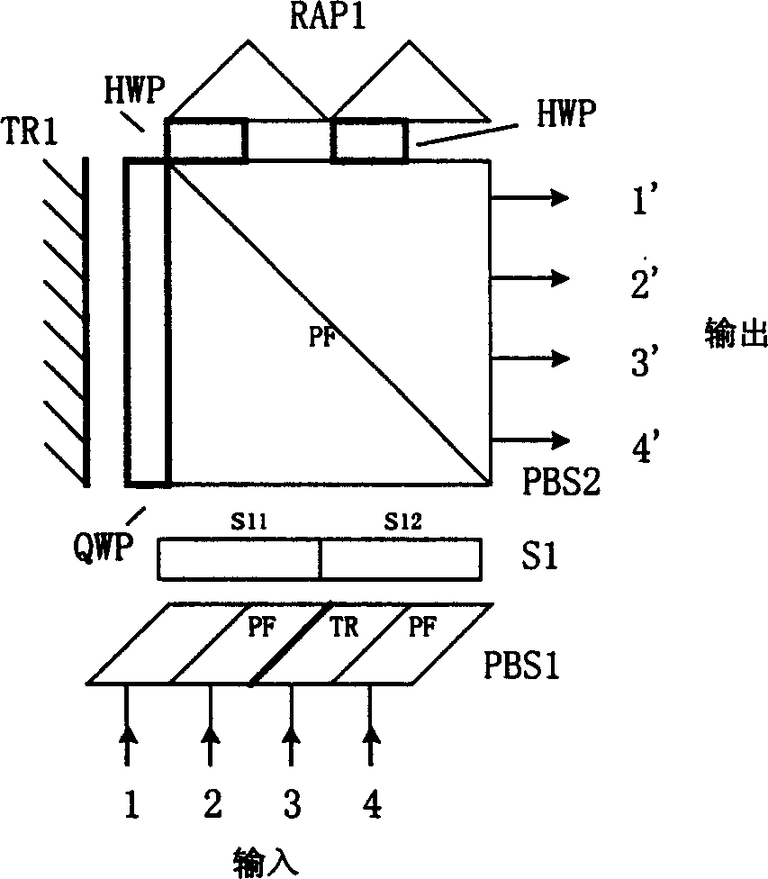
[0018] figure 1 It is a structural diagram of the dual-path 2×2 optical switch unit module of the present invention; it includes the first polarization beam splitting combination prism PBS1, the optical polarization controller array S1, the second polarization beam splitting combination prism PBS2; the second polarization beam splitting combination A λ / 4 wave plate QWP is attached to the vertical side of the prism PBS2, and there is a total reflection mirror TR1 at the opposite position; two λ / 2 wave plates HWP are attached to the horizontal side of the second polarization beam splitting combination prism PBS2, respectively. There is a right-angle combination prism RAP.

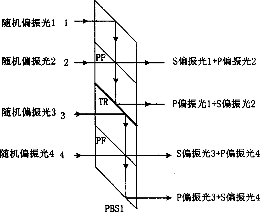
[0019] figure 2 is the polarization beam splitting optical path and polarization state change process of the first polarization beam splitting combination prism PBS1. The polarization plane PF represented by two 45° oblique lines in the first polarization beam splitting combination prism PBS1 is used to de...


PUM


Abstract

The invention is a two-way 2X2 optical switch and the 4X4 free space optical switch made up of the former one, which belongs to optical communication device, especially relates to optical passive device in full gloss communication network, the structure is compact, and it has no relation to polarization, the two-way 2X2 optical switch is only made up of polarization beam-splitting compound prism, lambda/4 wave plate, lambda/2 wave plate, direct angle prism, holophote and polarization light modulator, the 4X4 optical switch has light model structure, and it has no relation to the control of optical signal and the polarization state of the incidence beam. All the output ports and the input ports can interchange without obstacles. The structure is compact, and it can be widely applied to optical communication field.

Description

technical field [0001] The invention belongs to an optical communication device, in particular to an optical passive device of an all-optical communication network. Background technique [0002] With the rapid development of global communication traffic and the increase of communication service types, high-speed and large-capacity broadband ISDN has become an inevitable trend in the development of modern communication networks. The upper limit of the electronic signal processing rate is about 10Gbit / s. The traditional communication network based on electronic technology, because the rate of electronic devices is getting closer and closer to the physical and technical limit, further increasing the rate will greatly increase the system cost, so the current optical fiber transmission There is an electronic bottleneck caused by optical / electrical-electrical / optical conversion in the network, and the way out is to adopt a wide-band, large-capacity, high-speed Dense Wavelength Div...

Claims


Application Information

Patent Timeline
IPC IPC(8): G02B26/08
Inventor 罗风光曹明翠周新军罗志祥徐军
Owner HUAZHONG UNIV OF SCI & TECH
Why Eureka
Try Eureka