Integrated double end electric arc spraying equipment and spraying method

An electric arc spraying equipment and arc spraying technology, applied in liquid spraying devices, coatings, spraying devices, etc., can solve the problems of cumbersome spraying process, waste of resources and energy, and low spraying efficiency

Inactive Publication Date: 2005-03-16
HARBIN INST OF TECH
View PDF0 Cites 2 Cited by
  • Summary
  • Abstract
  • Description
  • Claims
  • Application Information

AI Technical Summary

Problems solved by technology

However, for spraying thicker coatings or spraying gradient coatings, as well as coatings with different performance requirements and different materials, it is not suitable for coatings. It is necessary to spray multiple times or readjust the specification p

Method used


Image

  • Integrated double end electric arc spraying equipment and spraying method
  • Integrated double end electric arc spraying equipment and spraying method
  • Integrated double end electric arc spraying equipment and spraying method

Examples


specific Embodiment approach 1

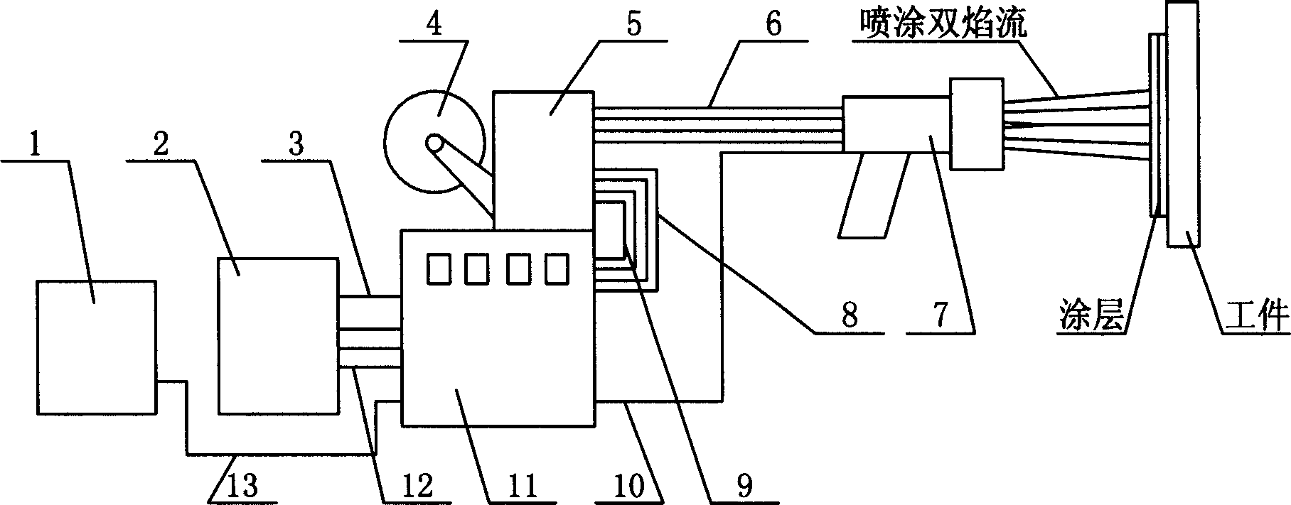
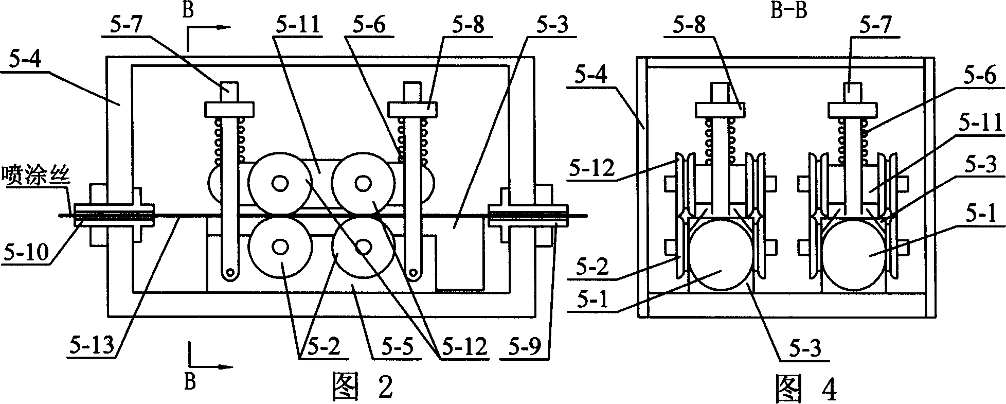
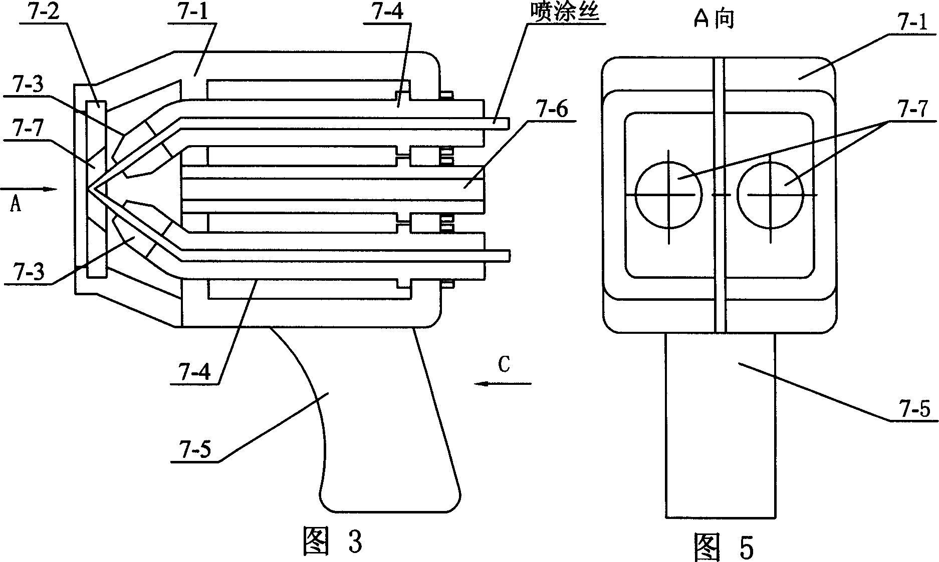
[0005] Specific implementation mode one: (see Figure 1-Figure 6 ) The integrated double-head arc spraying equipment in this embodiment consists of an air compressor 1, a spraying power supply 2, a No. 1 control line 3, a wire feeding reel 4, a wire feeding mechanism 5, a cable and a wire guide tube 6, a double-head spray gun 7, No. 2 output cable 8, No. 2 control line 9, No. 2 air compression pipe 10, control cabinet 11, No. 1 output cable 12, and No. 1 air compression pipe 13; the wire feeding mechanism 5 is fixed on the upper end of the control cabinet 11. The wire reel 4 is set on the wire feeding mechanism 5, the wire feeding mechanism 5 and the control cabinet 11 are connected by the second output cable 8 and the second control line 9, and the spraying power supply 2 and the control cabinet 11 are connected by the first control line 3 is connected with the No. 1 output cable 12, the No. 1 air compression tube 13 is connected between the air compressor 1 and the control c...

specific Embodiment approach 2

[0006] Specific implementation mode 2: This implementation mode is the preparation of anti-fatigue and high wear-resistant spray coating on the surface of a certain part of the power station equipment.

[0007] 1. Conditions: The material of this accessory is a brass component. It is used under the condition of 300 ° C. There is a slight abrasion and vibration during use. The coating is required to have certain anti-fatigue and anti-wear properties to ensure that the coating is in use. There must be no defects such as layering and block dropping that affect performance. The sprayed part is a rectangular plane, the coating area is 50mm wide and 100mm long, and the total thickness of the coating after grinding is 2mm.

[0008] 2. Coating design: According to the service conditions of the accessories, the size and shape of the coating and the quality requirements of the coating, a multi-layer bimetallic coating structure with a soft layer sandwiching a hard layer is selected. Co...


PUM

PropertyMeasurementUnit
Diameteraaaaaaaaaa
Thicknessaaaaaaaaaa
Thicknessaaaaaaaaaa

Abstract

The invention relates to a kind of arc spray device and spraying technology. A carrying wire plate is on the wire feeder of the device. Electric source for spraying connects to controlling box through size 1 controlling line and size 1 electric output cable. The controlling box connects to the double-spout spray gun through size 2 air-compressed tube. The wire feeder connects to the double-spout spray gun through electric cables and wire duct. Pressure of compressed air for spraying is 0.6Mpa to 0.8Mpa. The eclectic voltage for spraying is 20V to 35V .The electric current for spraying is 50A to 300A. The invention eliminates steps such as renewing painting material, adjusting technical parameter and so on .So it can save spraying time and raise working efficiency .The invention can be used to make mosaic laminating layers of different material and different performance, for example, thick base Ni3Al layer with thin mosaic WC layer .The invention has prominent advantages such as simple spray procedure, high spray efficiency, saving energy and resource and so on. The spraying method of this invention can be operated easily.

Description

Technical field: [0001] The invention relates to an electric arc spraying equipment and a spraying process. Background technique: [0002] Arc spraying is to melt two wires as electrodes through a short circuit, atomize the molten metal through compressed air and spray it onto the surface of the workpiece at high speed to form a coating. Compared with other spraying techniques, arc spraying has obvious advantages: ①The coating can achieve high strength and excellent coating performance. High bonding strength can be obtained without increasing the temperature of the workpiece and without using expensive primer materials. When spraying aluminum bronze, the self-adhesiveness of the coating is present, which further improves the bonding strength, and the bonding strength can reach 30MPa, which is generally 2.5 times that of the flame sprayed coating. ②The spraying efficiency is high, that is, the weight of the sprayed metal per unit time is large. ③ The energy-saving effect o...

Claims


Application Information

Patent Timeline
IPC IPC(8): B05B7/22B05D1/12B05D3/00
Inventor 郭面焕
Owner HARBIN INST OF TECH
Why Eureka
Try Eureka