
Display and dismountable light source structure thereof

A detachable, light source technology, applied in the direction of instruments, optics, nonlinear optics, etc., can solve problems such as cold welding, lamp tube leakage, and the inability to easily disassemble the lamp tube and wires

Active Publication Date: 2005-03-16
AU OPTRONICS CORP
View PDF0 Cites 1 Cited by
  • Summary
  • Abstract
  • Description
  • Claims
  • Application Information

AI Technical Summary

Problems solved by technology

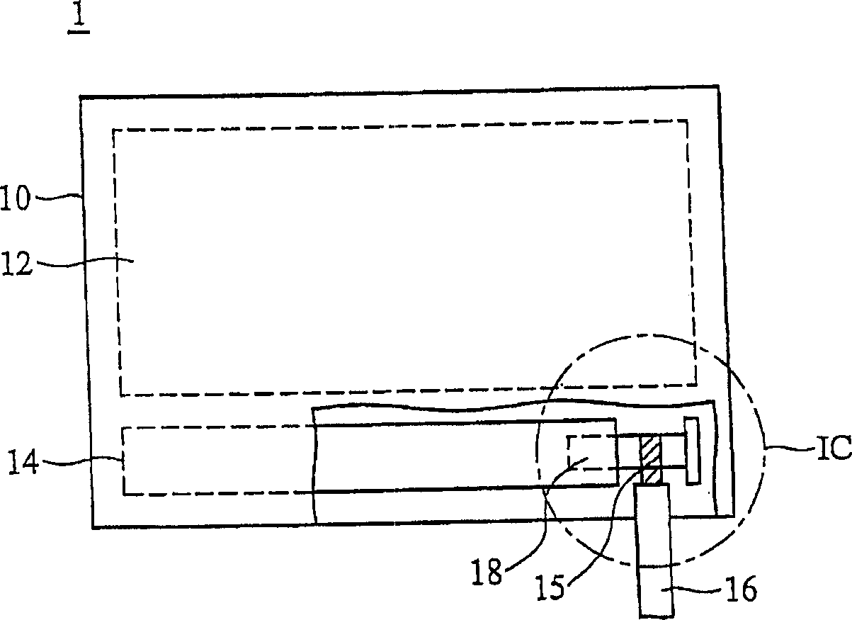
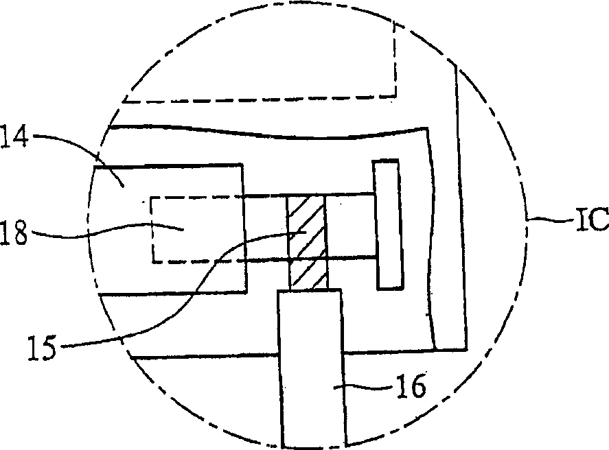
If the welding skills of the workers are not skilled enough, it is easy to cause false welding or cold welding. It is necessary to use X-ray to detect the welding part, otherwise it is difficult to judge whether it is a false welding
Therefore, it is difficult to grasp the stability of the connection between the electrode 18 and the wire 16.
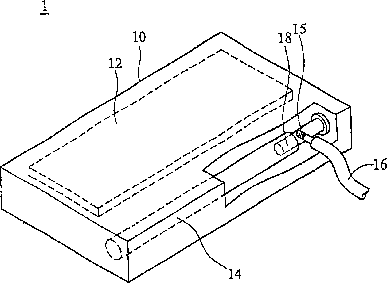
[0008] Because the wall thickness of the lamp tube 14 itself is relatively thin, under the high temperature of the soldering iron, the heat will be directly transferred to the lamp tube 14 near the electrodes. Tube (CCFL) leaks
[0009] In addition, since the electrodes 18 and the wires 16 are connected by soldering, if there is a problem with one of the lamps in a direct-lit backlight module with multiple lamps, the lamps and wires cannot be easily disassembled, so there is a problem of difficult processing.

Method used


Image

  • Display and dismountable light source structure thereof
  • Display and dismountable light source structure thereof
  • Display and dismountable light source structure thereof

Examples


no. 1 example

[0057] Figure 2A is an external perspective view showing a liquid crystal display 2 of the present invention, Figure 2B is based on Figure 2A A partially enlarged plan view of the lamp tube 24 and the wire 26 in the dotted line area IIB in . It should be noted that only one light tube 24 is shown in the figure as an example, and the present invention does not limit the quantity of the light tube 24 and the wires 26 .

[0058] Such as Figure 2A As shown, the display 2 includes a housing 20, a panel 22, a lamp (light source) 24, an electrode 28, a wire 26, a first joint 23 and a second joint 25, the panel 12 and the lamp 14 are jointly arranged in the housing 10, wherein the lamp tube 24, the electrode 28 and the wire 26 form a detachable light source structure, such as Figure 2B shown. The first coupling part 23 is fixedly connected to the electrode 28 , and the second coupling part 25 is fixedly connected to the wire 26 . The electrode 28 is electrically connected t...

no. 2 example

[0064] Figure 3B It is a partially enlarged and exploded schematic view showing the lamp tube 24 and the wire 26 of the second embodiment. In this embodiment, the same parts as those of the first embodiment will not be repeated, but the difference is that: the first coupling member 23' has a groove 230', and the groove 230' has a threaded surface 231', In other words, the first coupling member 23' is like a nut with internal threads. The second coupling part 25' is a protruding part with a threaded surface 251', that is, the second coupling part 25' is a screw. The insulation component 29' is covered on the second combination part 25'. The insulating component 29' can be made of silica gel or other materials, which can protect the connecting structure of the first coupling part 23' and the second coupling part 25' to prevent electric leakage.

[0065] The connection method of the lamp tube 24' and the wire 26' of the second embodiment will be described below.

[0066] Bef...


PUM


Abstract

It is a display and its detachable light source structure that comprises one light tube, one electrode, one first conjunction, one wire and second conjunction, wherein, the electrode is connected with light tube and the first conjunction comprises a first surface. The second conjunction comprises one-second surface and makes the wire electrically connected with the light tube through the second surface and first surface contacting.

Description

technical field [0001] The invention relates to a display, in particular to a display with a detachable light source structure capable of improving the joint strength between the lamp tube and the wire. Background technique [0002] Figure 1A It is an external perspective view showing a known liquid crystal display 1, Figure 1B is based on Figure 1A A plan view of the display structure 1, Figure 1C is based on Figure 1B A partially enlarged plan view of the lamp tube 14 and the wire 16 in the dotted line area IC in . [0003] As shown in Figures 1A and 1B, the liquid crystal display structure 1 includes a housing 10, a panel (panel) 12, a lamp (light source) 14, an electrode 18 and wires (wire) 16, the panel 12 and the lamp 14 are jointly arranged in the housing 10 . [0004] refer to Figure 1C , the electrode 18 is arranged in the lamp tube 14 and partially protrudes outside the lamp tube 14. The electrode 18 is electrically connected to the wire 16, and after th...

Claims


Application Information

Patent Timeline
IPC IPC(8): G02F1/13357
Inventor 孙开玙刘丞佑
Owner AU OPTRONICS CORP
Learn More