
Optical power adjusting method and apparatus

A technology of light quantity adjustment and light quantity, which can be applied to the exposure device of photoengraving process, recording/reproducing by optical method, printing device, etc., and can solve the problem of uneven concentration and other problems

Inactive Publication Date: 2005-03-16
FUJIFILM CORP
View PDF2 Cites 0 Cited by
  • Summary
  • Abstract
  • Description
  • Claims
  • Application Information

AI Technical Summary

Problems solved by technology

Therefore, there is a problem that even if the output value output from the light receiving element is corrected according to the wavelength of each laser beam as described above, and the light intensity of each laser beam is adjusted to be the same as each other, the photosensitive material is exposed to each laser beam and recorded. The density of the image on the photosensitive material also varies with each laser

Method used


Image

  • Optical power adjusting method and apparatus
  • Optical power adjusting method and apparatus
  • Optical power adjusting method and apparatus

Examples


no. 1 example

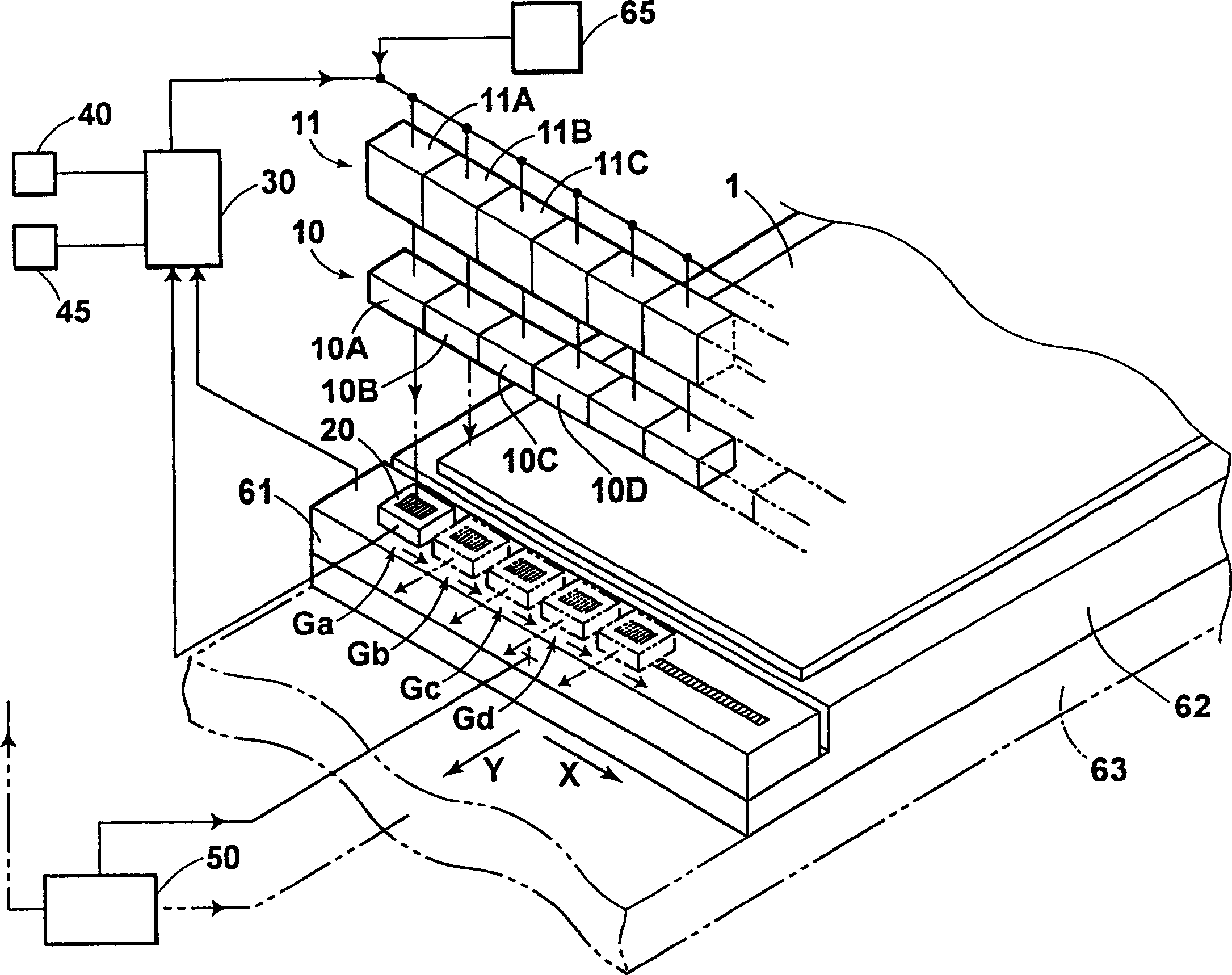
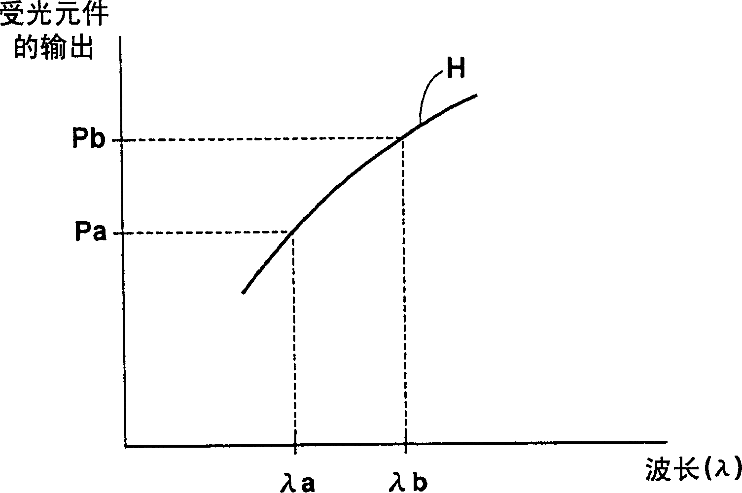
[0033] Next, a first embodiment of the present invention will be described with reference to the drawings. figure 1 It is a perspective view showing a schematic configuration of a light quantity adjusting device for carrying out the light quantity adjusting method according to the first embodiment of the present invention. figure 2 It is a graph showing the output wavelength relationship described later on the coordinate axis represented by the output value on the vertical axis and the wavelength on the horizontal axis.

[0034] The light quantity adjusting device of the present invention has the following parts: a plurality of laser irradiation parts 10A, 10B ... (the laser irradiation parts are collectively referred to as laser irradiation parts 10) as light irradiation means for exposing a photosensitive material, The light receiving unit 20 that receives the laser light that exposes the photosensitive material 1 and outputs an output value indicating the light quantity of...

no. 2 example

[0077] Next, a second embodiment of the present invention will be described with reference to the drawings. Figure 7 It is a perspective view showing a schematic configuration of an exposure apparatus equipped with a light amount adjustment device for implementing a light amount adjustment method according to a second embodiment of the present invention. Figure 8 It is a graph showing a predetermined constant output value output from the light receiving unit on a coordinate axis whose vertical axis is the output and whose horizontal axis is the wavelength. In addition, in the second embodiment, the same symbols as those in the first embodiment are used for the parts having common functions with those in the first embodiment.

[0078] The light quantity adjusting device 101 of the present invention mounted on the exposure device 100 has: a plurality of laser irradiation sections 10A, 10B... (each laser irradiation section is collectively referred to as a laser irradiation sec...


PUM


Abstract

An optical power adjusting method and apparatus for preventing unevenness of exposure of a photosensitive material arising from the difference in wavelength of the light beams. The relationship between the output value and wavelength of the light receiving section is stored in a storage section for a light beam that satisfies the relationship with respect to the optical power and wavelength required for exposing the photosensitive material at a predetermined exposure level. The correspondence between the laser beam emitting section and its wavelength is stored in another storage section. Each laser beam is received separately by the light receiving section, and the optical power of each laser beam is adjusted by the optical power adjusting section such that the output value of the light receiving section for each laser beam received separately satisfies the relationship between the output value and wavelength.

Description

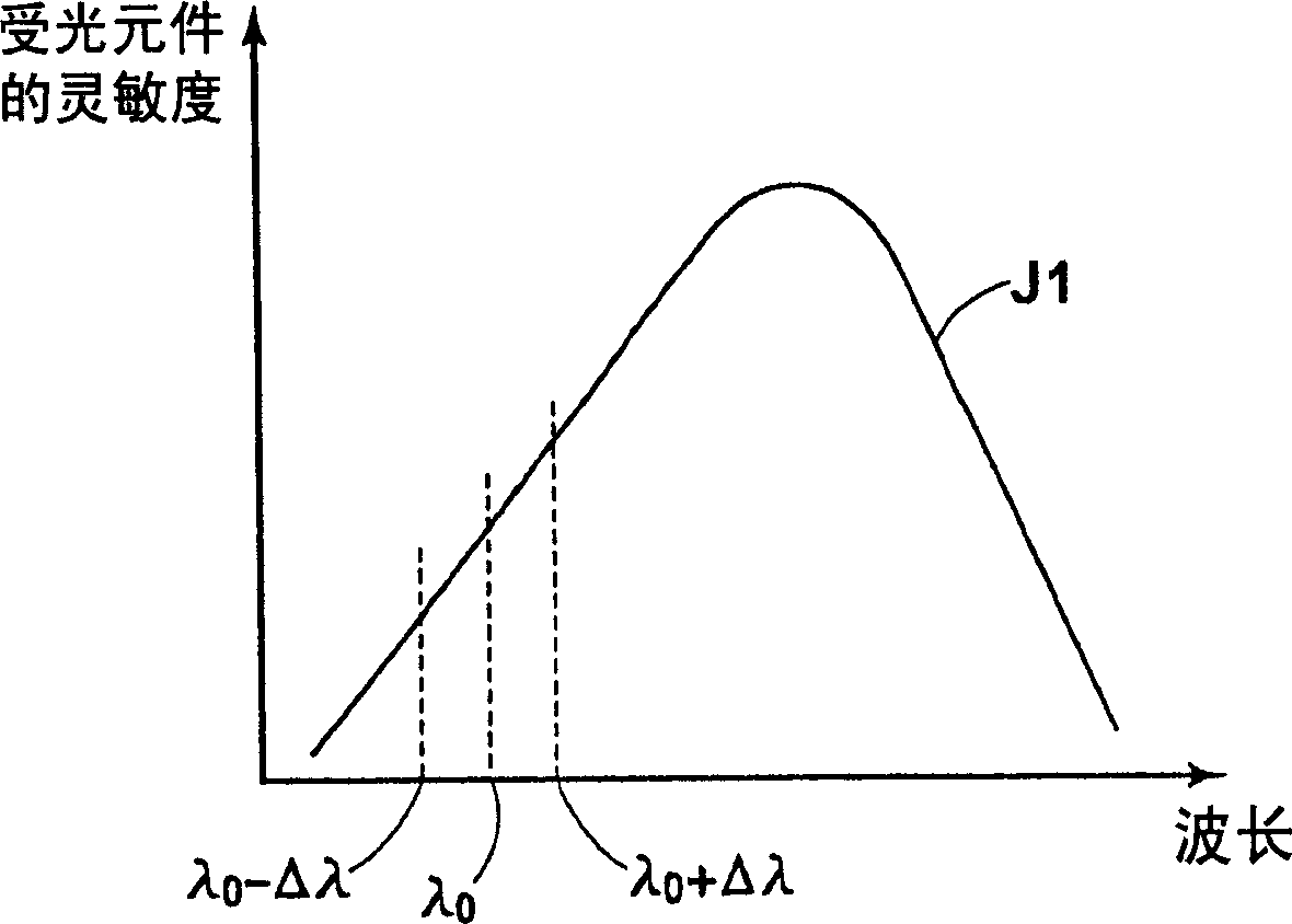
technical field [0001] The present invention relates to a light quantity adjustment method and device, in particular to an adjustment method and device for adjusting the light quantity of each light emitted from a plurality of light irradiation parts. Background technique [0002] Conventionally, image recording devices that record image information on a photosensitive material using laser light emitted from a plurality of laser light sources are known. In this device, the light intensity of each laser beam emitted from a plurality of laser light sources is measured using a light receiving element made of silicon as a main constituent material, and the light intensity of each laser beam is adjusted to a predetermined predetermined light intensity. In addition, as described above, the light receiving element using silicon as the main constituent material generally has different sensitivity depending on the wavelength of light received. That is, when the light receiving elemen...

Claims


Application Information

Patent Timeline
Patent Type & Authority Applications(China)
IPC IPC(8): G03F7/20G03B27/00G03B27/22G06K15/12G11B7/00
CPCG06K15/1214G03F7/20
Inventor 清水敦子角克人中谷大辅
Owner FUJIFILM CORP
Learn More