Casting method of vacuum thin wall

A vacuum and thin-wall technology, applied in the field of casting, can solve problems such as low vacuum degree, foam aluminum porosity, and yield problems

Inactive Publication Date: 2005-03-23
NANCHANG AERONAUTICAL ENG INST
View PDF0 Cites 9 Cited by
  • Summary
  • Abstract
  • Description
  • Claims
  • Application Information

AI Technical Summary

Problems solved by technology

The method of casting infiltration is currently used in the manufacture of new material aluminum foam. The casting mold of this method can be heated, and the molten metal above the casting mold is formed under vacuum suction, but because the vacuum degree in the casting mold cavity is not high when filling the mold , the molten metal

Method used


Image

  • Casting method of vacuum thin wall

Examples


Embodiment Construction

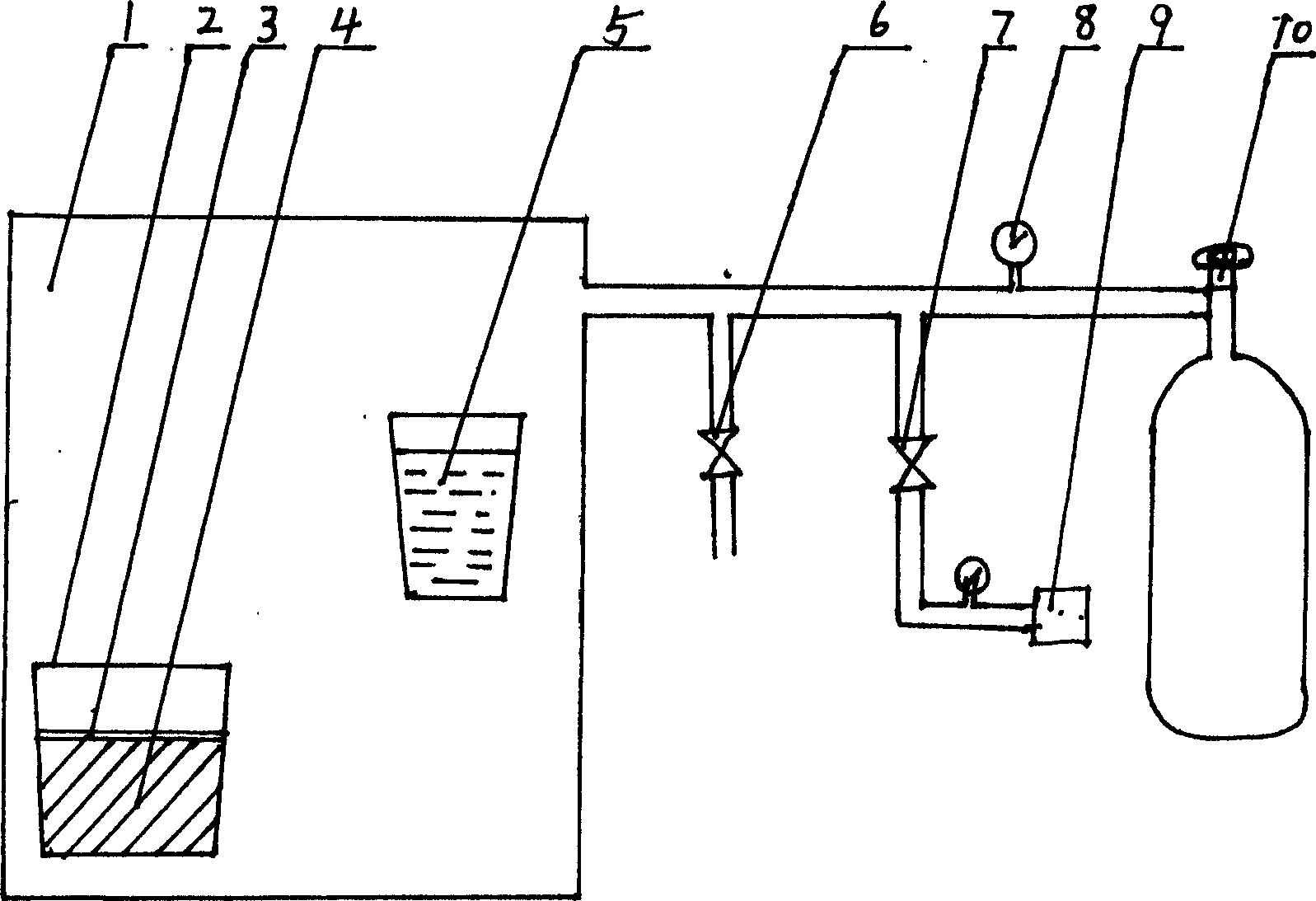
[0008] Such as figure 1 As shown, the mold (4) is put into the temperature-resistant container (2), and the limit frame (3) is placed on the top of the mold, and the temperature-resistant container (2) and a sufficient amount of molten metal (5) Put them into the vacuum chamber (1), close the atmospheric valve (6), open the vacuum valve (7), and vacuumize with the vacuum pump (9). 5) Pour into the temperature-resistant container (2), the liquid metal will surround the mold (4), close the vacuum valve (7), stop vacuuming, open the atmospheric valve (6) to break the vacuum, and the atmospheric pressure will press the liquid metal into the mold In the cavity of the type, when additional pressure is required for operation, the atmospheric valve (6) can be closed, the switch of the high-pressure tank can be turned on, and the air source of the high-pressure tank can be pressed into the vacuum chamber, and additional pressure can be established on the vacuum liquid level. , can con...


PUM


Abstract

A vacuum casting method for casting thin wall includes such steps as putting mould in a refractory container, making the mould in vacuum condition, surrounding the mould by sufficient molten metal and removing the vacuum condition to fill the molten metal in moulding cavity by atmosphere pressure.

Description

technical field [0001] The invention relates to a casting method, especially a vacuum thin-wall casting method. Background technique [0002] In the existing special casting methods, differential pressure casting and investment casting can only produce castings with a wall thickness of 0.5 to 1mm, and the production efficiency of differential pressure casting is not high. High temperature, but the pressure head of its filling is not high. Because the filling pressure head will affect the liquid metal filling ability and affect the formation of thin-walled castings. Above-mentioned two casting methods all have respective deficiency. The method of casting infiltration is currently used in the manufacture of new material aluminum foam. The casting mold of this method can be heated, and the molten metal above the casting mold is formed under vacuum suction, but because the vacuum degree in the casting mold cavity is not high when filling the mold , the...

Claims


Application Information

Patent Timeline
IPC IPC(8): B22D18/06
Inventor 胡美忠蔡长春
Owner NANCHANG AERONAUTICAL ENG INST
Why Eureka
Try Eureka