Drill kind electric tool

A technology of electric tools and working heads, which is applied in the direction of manufacturing tools, portable drilling rigs, portable mobile devices, etc., can solve the problems of unspecified drilling electric tools, etc., and achieve the effect of improving efficiency and accuracy

Inactive Publication Date: 2005-03-23
POSITEC POWER TOOLS (SUZHOU) CO LTD
View PDF1 Cites 14 Cited by
  • Summary
  • Abstract
  • Description
  • Claims
  • Application Information

AI Technical Summary

Problems solved by technology

[0004] But above prior art all does not provide a kind of drilling type electric tool with laser level instrument, this laser level instrument just can provide accurate drilling work directly on the workpiece surface under the state that is connected with drilling type electric tool main body. In addition, the laser level can also be easily removed from the drill power tool at any time, and placed on the working reference surface to be used as an indicating device for drilling, hammering, cutting, etc.

Method used


Image

  • Drill kind electric tool
  • Drill kind electric tool
  • Drill kind electric tool

Examples


Embodiment Construction

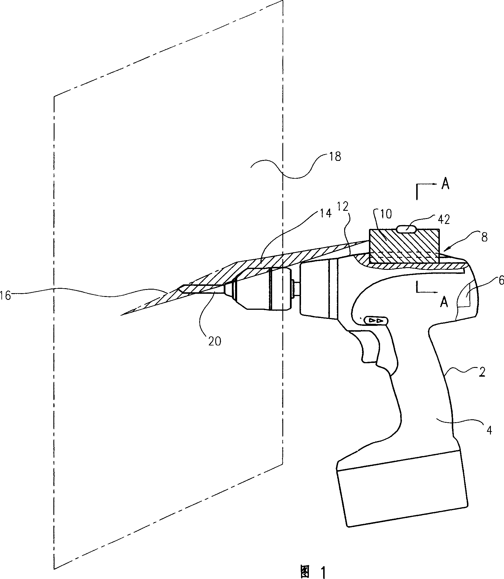
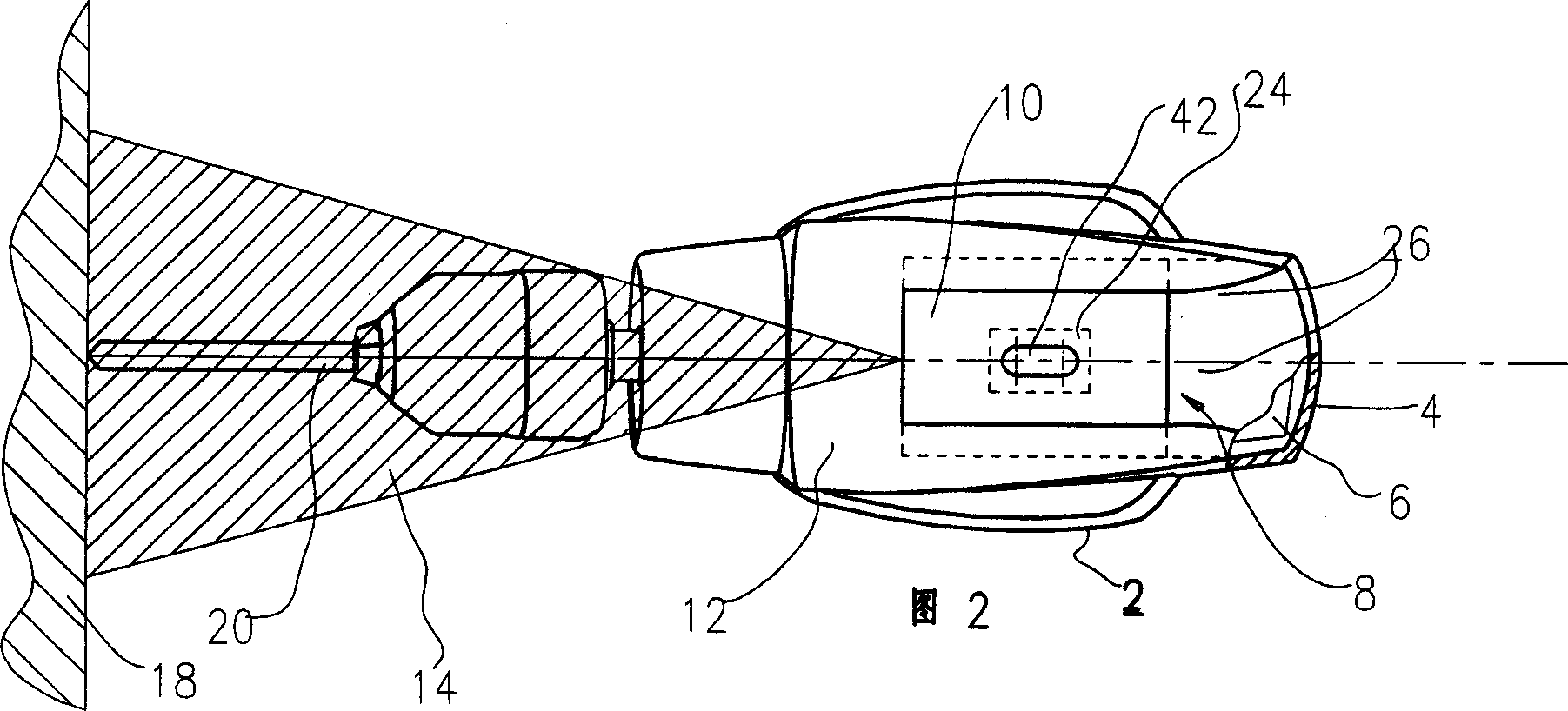
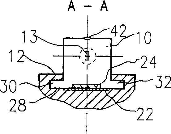
[0023] Please refer to Figure 1 to image 3 , an electric drill 2, comprising a housing 4, a motor 6 accommodated in the housing 4, a laser level 10 operable to emit a laser 14, a connecting device 8, the connecting device 8 connects the laser level 10 is connected to the housing 4 and the connection device 8 is arranged on the top shell 12 of the housing 4 .

[0024] A working head 20 is installed on the chuck at the front end of the drill, such as the traditionally used chuck of the current electric drill, the chuck can be keyless, or a chuck that requires a corresponding key.

[0025] When the laser level 10 is in the open state, when the laser tube (not marked) on the laser level is projected from the mouth 13 to guide the surface of the workpiece, a mark can be formed on the work surface. The marks formed are just aligned with the frontmost end of the working head 20, thus providing clear marks of alignment and instructions for the operator.

[0026] In a preferred embod...


PUM


Abstract

A drill-type electric tool able to aligning the drilled holes is composed of a casing, a motor in the casing, a laser leveler able to emit laser beam, and a jointer for joining said laser level indicator to the top of casing.

Description

technical field [0001] The invention relates to a drill electric tool, in particular to a drill electric tool with a laser level. Background technique [0002] A kind of drill can be bought on the market, the handle place of this drill is provided with a storage room, and a laser level is accommodated in this storage room. In this design, the laser level can be easily installed in the storage room, and can be easily removed from the storage room when in use. The laser level is installed in the storage room on the handle to make it easy to carry. When in use, the laser level needs to be removed from the drill and placed on the working reference surface to open, and the laser marking can be used to provide instructions for drilling work. The disadvantage of this design is that the laser level cannot be installed on the drill and work with the drill at the same time. It needs to be taken off from the drill and fixed on the working surface in addition, which increases the compl...

Claims


Application Information

Patent Timeline
Patent Type & Authority Applications(China)
IPC IPC(8): B23B45/02B23K26/36B25F5/02
Inventor 朱世燕
Owner POSITEC POWER TOOLS (SUZHOU) CO LTD
Why Eureka
Try Eureka