
Compacting and plastering machine for concrete surface

A concrete surface and troweling machine technology, which is applied in the direction of construction and building construction, can solve the problems of low work efficiency and footprints, and achieve the effect of high work efficiency

Inactive Publication Date: 2005-03-23
周德平
View PDF0 Cites 20 Cited by
  • Summary
  • Abstract
  • Description
  • Claims
  • Application Information

AI Technical Summary

Problems solved by technology

The disadvantage of this kind of hand-held troweling machine is that the footprints made by the operator on the concrete surface are relatively deep, and it takes a certain period of time to wipe them repeatedly to smooth the footprints. Aggregate, after the concrete moisture volatilizes and the slurry shrinks, footprints will still appear; in addition, the existing troweling machine only has one set of reactionary troweling components, and the work efficiency is low. When the temperature is high and the concrete solidifies quickly, Or in the case of a large amount of concrete pouring, it is difficult to complete the required work surface in time, and it is necessary to allocate a large amount of manpower or organize several trowel machines to complete the required work surface at the same time

Method used


Image

  • Compacting and plastering machine for concrete surface
  • Compacting and plastering machine for concrete surface
  • Compacting and plastering machine for concrete surface

Examples


Embodiment Construction

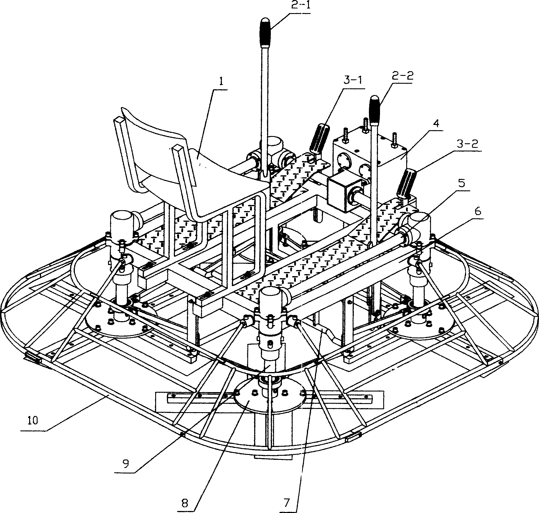
[0023] The following is based on Figure 1 to Figure 10 The specific embodiment of this trowel will be described.

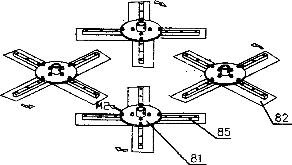
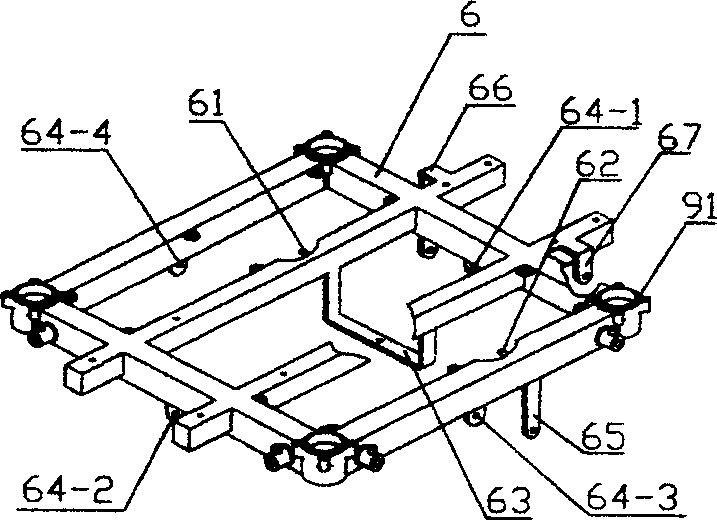
[0024] figure 1 Middle, 1-seat, 2-1-front and rear travel handle, 2-2-steering handle, 3-1-left travel pedal, 3-2-right travel pedal, 4-reducer, 5-power Transmission system, 6-frame, 7-travel linkage mechanism, 8-smearing component, 9-vertical transmission shaft, 10-protective cover, 91-bearing shell; figure 2 Middle, 81-blade fixed base, 82-smoothing blade, 85-blade reinforcing strip; image 3 Among them, 61, 62, 63, 64, 64-1, 64-2, 64-3, 64-4, 65, 66, 67 are respectively the connection points of the corresponding components of the linkage mechanism, which will be explained together with FIG. 8 .

[0025] figure 1 Represent the overall structure embodiment of troweling machine of the present invention, below in conjunction with figure 2 with image 3 right figure 1 Be explained. figure 1 The four groups of wiper components 8 are made up of a blade fixi...


PUM


Abstract

The invention relates to a concrete layer compacting and polishing and squeegee machine, which includes power gearing system, four groups of squeegee components, square frame with seat and mobile linkage mechanism. The squeegee component includes four squeegee blades, the four groups of squeegee components are fixed on the four corners of the square frame through vertical gearing spindle, the four vertical gearing spindles rotates the two adjoined spindles reversely through the power gearing system, the two spindles on the cross rotate with the same direction; the mobile linkage mechanism is made up of lengthwise and transverse spindles and crank arms, cranks. The mobile linkage mechanism drives the subjacent part of the vertical gearing shaft to shift along the radial direction through manual or foot pedaling operations, the resistance is increased when the squeegee blade is transferred to another side, the resistance of another side is decreased.

Description

technical field [0001] The invention relates to a concrete surface layer compacting and troweling machine, which is used for compacting and troweling the concrete or cement mortar surface layer before solidification, and belongs to construction machinery. Background technique [0002] In the construction of concrete or cement pavement and ground, the surface needs to be compacted and troweled before solidification. Existing troweling machine is made up of power machine, speed reducer, a group of troweling assembly and push handle etc. The troweling assembly contains four troweling blades which are slightly angled to the ground, that is, the rear side of the blade is on the ground, and the front side is off the ground (the side facing the direction of rotation is the front side). When working, the operator stands on the concrete and holds the handle to push the trowel to walk. The surface over which the blade rotates is smoothed or smoothed. The disadvantage of this kind o...

Claims


Application Information

Patent Timeline
IPC IPC(8): E04F21/16E04F21/24
Inventor 周德平
Owner 周德平
Learn More