Energy controlling method in electronic beam machining

A technology of electron beam processing and energy control, which is applied in the direction of electron beam welding equipment, metal processing equipment, manufacturing tools, etc., and can solve problems such as no energy density control method is given

Inactive Publication Date: 2005-04-06
SHANGHAI JIAO TONG UNIV +1
View PDF1 Cites 7 Cited by
  • Summary
  • Abstract
  • Description
  • Claims
  • Application Information

AI Technical Summary

Problems solved by technology

Using this technology, the purpose of making the electron beam move according to the set scanning trajectory can be achieved, but the patent does not give the energy density control method

Method used


Image

  • Energy controlling method in electronic beam machining
  • Energy controlling method in electronic beam machining
  • Energy controlling method in electronic beam machining

Examples


Embodiment 1

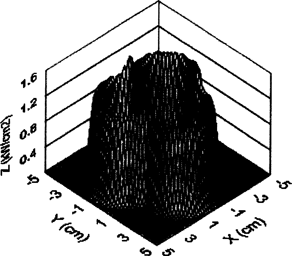
[0050] Example 1: Energy density control of a single scanning trajectory through the number of points

[0051] In this embodiment, a single scanning track is controlled by the number of scanning points along the length direction of the scanning track, and the energy density is controlled at different positions of the scanning track.

[0052] use as figure 1 The scanning track shown requires that the energy density of the electron beam is uniformly distributed along the length of the scanning track. According to the above requirements, it is preliminarily determined that the scanning points are evenly distributed along the length direction of the scanning track, and the number of scanning points in one scanning cycle is 660.

[0053] The surface of the workpiece is divided into discrete points, and 50×50 points are divided, that is, both M and N are equal to 50 in the energy density distribution matrix. Using the aforementioned energy density calculation method, the energy de...

Embodiment 2

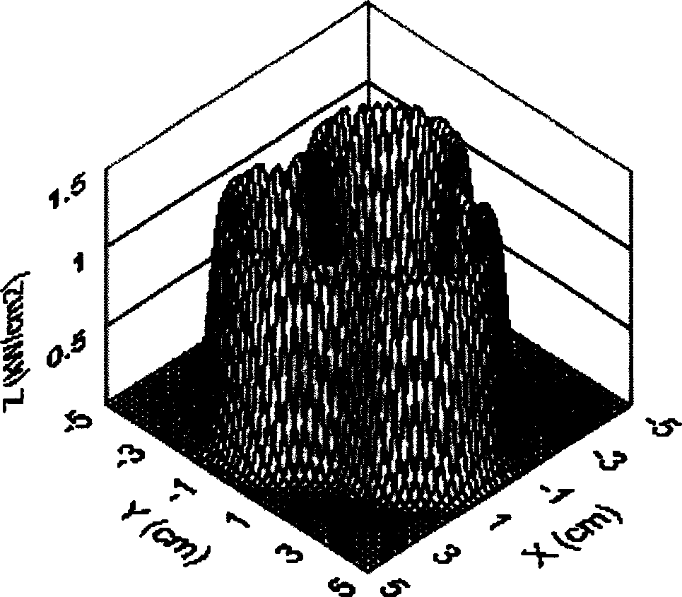
[0055] Embodiment 2: Energy density control of a single scanning track through beam current

[0056] In this embodiment, energy density is controlled at different positions of the scanning track by controlling the beam current along the length direction of the scanning track for a single scanning track.

[0057] use as Figure 4 The scanning trajectory shown requires the electron beam energy density distribution as Figure 5 As shown, it varies uniformly along the length of the scanning track. According to the above requirements, the scanning points are uniformly distributed along the length direction of the scanning track, and the beam current value changes uniformly at different positions of the scanning track. The number of scanning points in one scanning cycle is 500.

[0058] The surface of the workpiece is divided into discrete points, and 50×50 points are divided. Continuously changing beam current: in one cycle of the scanning trajectory, the beam current gradually ...

Embodiment 3

[0059] Example 3: Energy density control of two scanning trajectories through the number of points

[0060] The scanning trajectory of the electron beam is in the form of two concentric circles, such as Figure 6 As shown, and requires the energy density of the small circle to be lower than that of the large circle.

[0061] Preliminarily determine the number of small circle scanning points: 200, the number of large circle scanning points: 350, divide the surface of the workpiece into discrete points, and divide 50×50 points. Using the aforementioned energy density calculation method, the obtained energy density distribution shows that the energy density of the small circle is slightly higher than that of the large circle, which does not meet the requirements, so it is necessary to reduce the number of points of the small circle or increase the number of points of the large circle. Now reduce the number of small dots to 150 and keep the number of big dots unchanged, then the ...


PUM


Abstract

The invention relates to electron beam machining energy control method which is used in materials processing. According to the distributing demand of the energy density at the work piece, the number of the scanning point in each position of the scanning trace is distributed or the flow value of the electron beam is controlled, or both of the methods are adopted at the same time to control the energy density of the heated work piece surface. Then the required energy density distribution is gained at the surface of the heated work piece. Heterogeneous metal are welded by respectively controlling the amount of the scanning point at the both sides of the joint, the distribution of the scanning point, and the flow value of the electron beam to control the energy input at the both sides of the joint, so that the molten charge of the heterogeneous metal is adjusted at the both sides of the joint. The invention realizes the energy density control at the different position of the scanning trace, can respectively practice energy density control to each scanning trace at the condition that the scanning traces are many, and can effectively control the molten charge of the heterogeneous metal at the both sides of the joint while welding the heterogeneous metal.

Description

technical field [0001] The invention relates to an energy control method in material processing, in particular to an energy control method for electron beam processing and electron beam welding of dissimilar metals. Used in the field of material processing. Background technique [0002] When electron beams are used as heat sources to process materials, the energy input and energy density distribution on the workpiece is an important factor that determines the characteristics of the temperature field of the workpiece. Usually, the scanning trajectory of the electron beam has different shapes and forms according to the different requirements of the workpiece to be heated. When a certain electron beam scanning trajectory is used to heat the workpiece, especially when the scanning trajectory is relatively complicated, the scanning trajectory The interaction between the various parts, the difference in the curvature of different parts of the scanning trajectory, and the differen...

Claims


Application Information

Patent Timeline
Patent Type & Authority Applications(China)
IPC IPC(8): B23K15/00B23K15/02
Inventor 王学东朱智春芦凤桂戴德海唐新华
Owner SHANGHAI JIAO TONG UNIV
Why Eureka
Try Eureka