Interlaminar bonding strength tester for pavement

A technology for bonding strength and pavement interlayers, applied to instruments, using stable shear force to test material strength, using stable tension/pressure to test material strength, etc., can solve the problem of inconvenient carrying test, bulky instrument, and poor function Single and other problems, to achieve the effect of accurate and reliable test data, convenient portability and simple structure

Inactive Publication Date: 2005-04-06
HENAN GAOYUAN ROAD MAINTENANCE EQUIP
View PDF0 Cites 20 Cited by
  • Summary
  • Abstract
  • Description
  • Claims
  • Application Information

AI Technical Summary

Problems solved by technology

[0005] The above-mentioned tensile and shear force instruments for testing asphalt mixture specimens have a single function and cannot be used to test both tensile force and shear force, and the instruments are heavy and inconvenient to be carried in the field for testing

Method used


Image

  • Interlaminar bonding strength tester for pavement
  • Interlaminar bonding strength tester for pavement
  • Interlaminar bonding strength tester for pavement

Examples


Embodiment 1

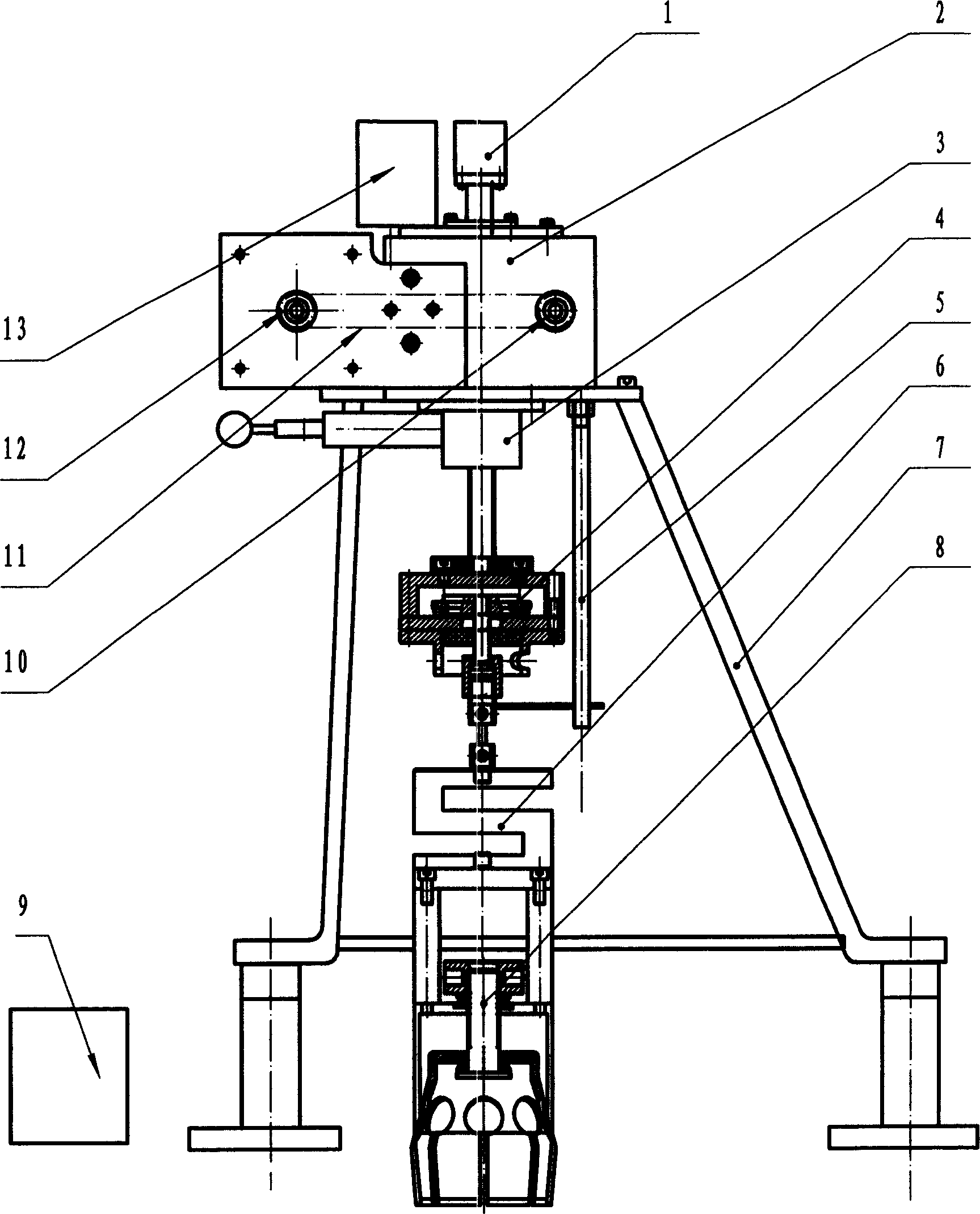
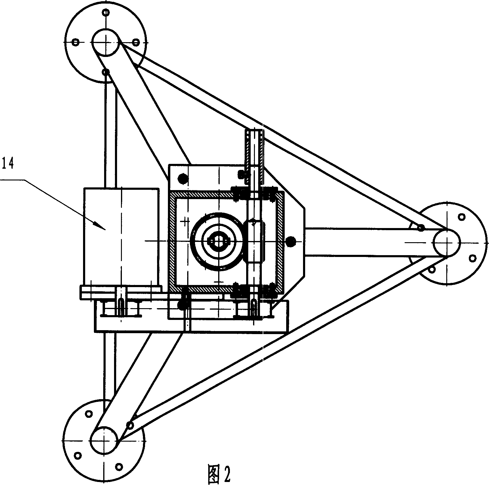
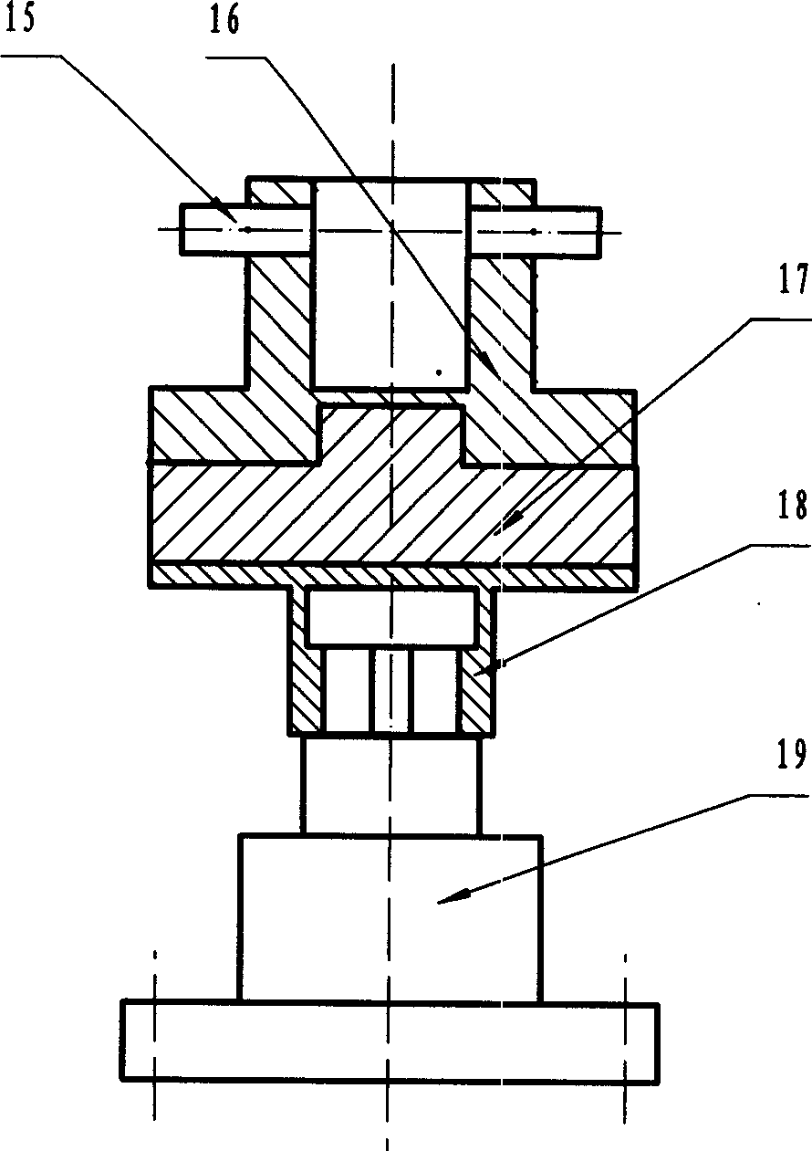
[0021] exist figure 1 , 2, 3, the pavement interlayer bonding strength tester of the present embodiment is composed of photoelectric encoder 1, speed reducer 2, control mechanism 3, eccentric conversion mechanism 4, torque balance bar 5, tension sensor 6, frame 7 , clamping mechanism 8, computer 9, driven sprocket 10, chain 11, driving sprocket 12, programmable controller 13, motor 14, pin 15, upper half coupling 16, cross coupling body 17, lower half Shaft coupling 18 and torque sensor 19 are connected to form, wherein pin 15, upper half coupling 16, cross coupling body 17, and lower half coupling 18 are connected into a shaft coupling.

[0022] The left side on the frame 7 is fixedly installed with a motor 14 with a threaded fastening connector, and the motor 14 provides power for the present invention, and the right side on the frame 7 is fixedly connected with a speed reducer 2 with a threaded fastening connector, and the motor The drive sprocket 12 is installed on the ou...

Embodiment 2

[0029] The central position of the lower backing plate 4-7 of the eccentric conversion mechanism 4 in this embodiment is processed with a 22mm center hole, and the outer diameter of the pull rod 4-4 is 12mm. Other components and the coupling relationship of the components are the same as in Embodiment 1.

Embodiment 3

[0031] The center position of the lower backing plate 4-7 of the eccentric conversion mechanism 4 in this embodiment is processed with a 36mm center hole, and the outer diameter of the pull rod 4-4 is 18mm. Other components and the coupling relationship of the components are the same as in Embodiment 1.


PUM


Abstract

It is a road surface binding strength test device, which is located with a motor on left side and a decelerator connected with motor through the transmission structure on right side. The decelerator is located with photoelectricity coder and programmable controller, which are connected with computer through cable and photoelectricity coder. There locate moment balance bar and control structure with its top connected with decelerator and its bottom connected with eccentric mechanism on the rack. The bottom of the eccentric mechanism is located with a pull sensor or torque sensor connected with clutch. There locate a clamping structure on the pull sensor or bottom of torque sensor.

Description

technical field [0001] The invention belongs to the technical field of force measuring equipment, and in particular relates to a tester for the bond strength between pavement layers. Background technique [0002] The structure of the asphalt pavement is generally to pave the asphalt mixture surface layer on the semi-rigid base layer stabilized by cement or fly ash. The asphalt mixture is generally used as the pavement layer on the bridge surface. The bonding between the asphalt surface layers, between the surface layers, and between the asphalt pavement layer and the cement bridge deck is very important. [0003] The instrument specially used to test the tensile force of asphalt pavement or bridge deck is the bridge deck waterproof layer puller, which is powered by a motor and adopts the structure and principle of a screw lifter. During the test, the lower end of the asphalt mixture specimen is fixed on the fixture, and the screw lifter structure pulls The upper end of the ...

Claims


Application Information

Patent Timeline
Patent Type & Authority Applications(China)
IPC IPC(8): G01N3/12G01N3/24G01N19/04
Inventor 刘廷国赵永利孟海平
Owner HENAN GAOYUAN ROAD MAINTENANCE EQUIP
Why Eureka
Try Eureka