
Optical fiber wiring system

A technology of optical wiring and optical fiber, which is applied in the field of optical wiring system, can solve problems such as complex state of optical fiber cord, increased optical loss, deformation of optical fiber cord, etc., so as to avoid overcrowded wiring path, improve operation efficiency, and improve operational effect

Inactive Publication Date: 2005-04-20
NIPPON TELEGRAPH & TELEPHONE CORP
View PDF1 Cites 3 Cited by
  • Summary
  • Abstract
  • Description
  • Claims
  • Application Information

AI Technical Summary

Problems solved by technology

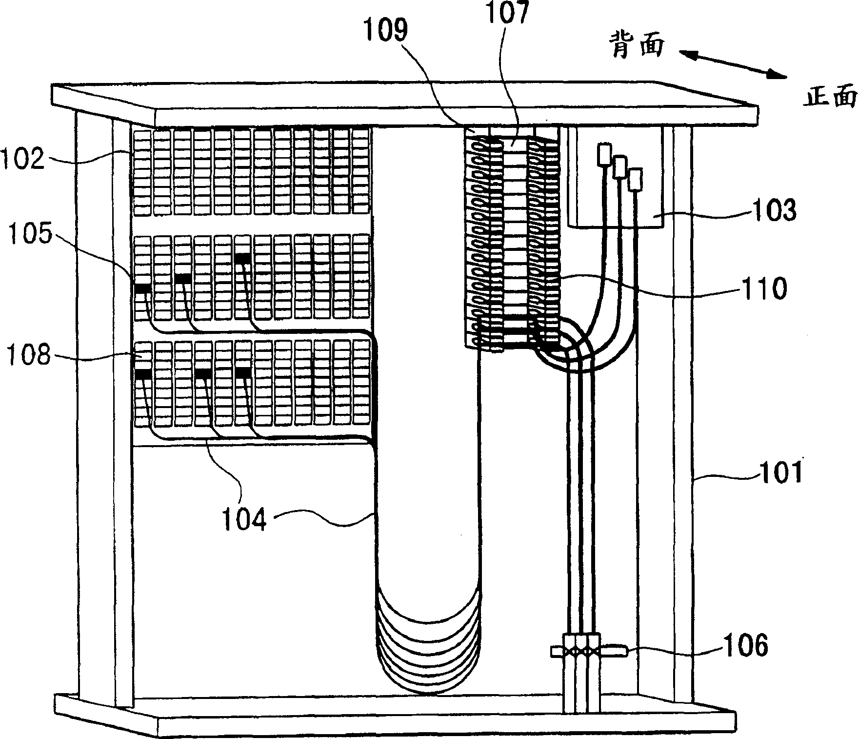
[0007] However, when these operations are repeated, since a plurality of optical fiber cords are entangled, there are problems such as the following, and the high density of the optical distribution panel cannot be realized, namely
[0008] 1. As the number of repetitions of the above operations increases, the tangled state of the optical fiber cords becomes very complicated, so that the optical fiber cords cannot be connected to any position of the wiring board;
[0009] 2. A single optical fiber cord bears the load of other optical fiber cords, thus deforming the optical fiber cord;
[0010] 3. Similarly, the force applied to the optical fiber cord is transmitted to the connection part of the optical connector plug at the front end of the optical fiber cord, thus increasing the optical loss
When it is necessary to convert and connect the optical fibers of the user optical cable and the intra-office optical cable due to construction projects or fault repair projects, in order to untangle the converted optical fiber and other optical fibers and prevent false cuts, it is necessary to spend on this operation. long time

Method used


Image

  • Optical fiber wiring system
  • Optical fiber wiring system
  • Optical fiber wiring system

Examples


no. 1 Embodiment

[0115] Fig. 15 is a diagram showing the structure of an intra-office device including an integrated optical distribution system, Figure 16 It is a diagram for explaining the connection form of the integrated optical distribution system and other equipment located in the equipment center.

[0116]In the figure, 401 is an integrated optical distribution system, 402 is an optical coupler, 403 is a fiber selection device (FS), 407 is a communication system optical subscriber line terminal office device, 408 is an image system optical subscriber line terminal office device, 409 is an optical subscriber line terminal office device placement frame, 410 is a star coupler frame, 411 is a test device frame (TEM), 415 is the first intra-office optical cable, 417 is a user system optical cable, 426 is a test access function part, 427 428 is the splitter function part, 429 is the optical distribution function part, 430 is the optical fiber selection function part, 431 is the operation sup...

no. 2 Embodiment

[0122] In this embodiment, the optical test function part 472, the monitoring function part 473, the optical fiber checking function part 474, and the tester selection function part 471 for selecting the optical testing function part, the monitor function part and the fiber checking function part are constituted. The optical test assembly 411 is connected to the fiber selection function part 430 . The optical test function unit 472 has the function of optically testing the optical fiber of the optical cable, the monitoring function unit 473 has the function of monitoring communication light and test light, and the fiber checking function unit 474 has the function of checking the optical fiber. According to this embodiment, it is possible to perform a test when newly installing the user system optical cable 417 and a test for maintenance.

no. 3 Embodiment

[0124] Figure 17 and Figure 18 , is a diagram for explaining the third example of this embodiment. In the figure, 440 is the basic component of IDM436, 441 is the extension component of IDM436, 442 is the test access unit, 443 is the positioning plate, 444 is the holding plate unit, 445 is the plug-in optical fiber, 446 is the wiring unit, 447 is the The junction plate, 448 is the fixing part of the intra-office optical cable, 449 is the holding plate, and 450 is the third intra-office optical cable.

[0125] The basic component 440 of the IDM436 in this embodiment has a test access function part 426, a cross-connect function part 427, a splitter function part 428, an optical wiring function part 429, and an optical fiber selection function part 430, and an additional component 441 has Test the access function part 426 , the cross-connect function part 427 , the splitter function part 428 and the fiber selection function part 430 . The test access component 442 has a test...


PUM


Abstract

The present invention provides an optical distribution system, which is provided with: a termination function part on the side of the terminal office device, which is used to terminate a plurality of first optical cables connected to the terminal station device of the optical subscriber line; a termination function part on the side of the terminal device, used for It is used to terminate the second optical cable connected with multiple optical user terminal devices; the cross-connect function part is used to switch any optical fiber of the above-mentioned first optical cable and any optical fiber of the above-mentioned second optical cable; the optical distribution function part uses In order to connect any optical fiber drawn from the above-mentioned end station device side termination function part to a plurality of the above-mentioned cross-connection function parts; A test access function unit for input and output of test light, and an optical fiber selection function unit for selecting a test light input / output port of the test access function unit.

Description

[0001] This application is a divisional application of the original application with the application number 99111397.7 and the filing date on July 24, 1999. The earlier application number of the original application is JP209453 / 98 and the earlier application date is July 24, 1998. technical field [0002] The present invention relates to a distribution board for connecting or switching multi-core optical fiber cords with connectors, an optical fiber cord and an integrated optical fiber cord using the cords, and a device for managing the connection between optical fibers outside the facility and those inside the facility. An optical wiring system that transmits information on optical wiring for connection between devices and effectively uses optical wiring. Background technique [0003] The existing optical distribution board is equipped with a connector wiring board equipped with a plurality of optical connector adapters and a reservation board for retaining unconnected optic...

Claims


Application Information

Patent Timeline
IPC IPC(8): G02B6/46G02B6/44H04Q1/14
CPCG02B6/4452G02B6/4482H04Q1/14H04Q1/20G02B6/46
Inventor 宇留野重则立蔵正男泉田史峰恒司榎本圭高中尾直树富田信夫广冈明武本一
Owner NIPPON TELEGRAPH & TELEPHONE CORP
Learn More