Power supply method and connection configuration for train power network on magnetic suspension train without power tracks

A vehicle-mounted power grid and maglev train technology, which is applied to current collectors, electric vehicles, vehicle components, etc., can solve the problems of high infrastructure costs for maglev train lines, reduce the efficiency of high-power repeated discharge, and increase the workload of inspection and maintenance. The effect of maintenance workload, easy promotion and use, and long continuous working hours

Inactive Publication Date: 2005-04-27
TONGJI UNIV
View PDF0 Cites 7 Cited by
  • Summary
  • Abstract
  • Description
  • Claims
  • Application Information

AI Technical Summary

Problems solved by technology

The high-conductivity wear-resistant alloy material used for the power supply rail is expensive in itself, and the quality requirements for laying it are high, so the infrastructure cost of the maglev train line is high
At the same time, in the low-speed road section, the current receiver is in frequent contact with the power supply rail, the sliding friction loss is large, the workload of inspection and maintenance is also increased, and the operation and maintenance costs are correspondingly increased.
As we all know, nickel-cadmium batteries have a strong memory effect, and the working state of shallow charge and shallow discharge will greatly reduce their high-power repeated discharge efficiency. Therefore, the existing maglev trains only use the on-board nickel-cadmium batteries as a backup for train eddy current emergency braking. For power supply, each car is equipped with 8 440V, 27Ah nickel-cadmium battery boxes (each box is composed of 1.2V, 27Ah single-cell nickel-cadmium batteries connected in series), and the total storage energy is 47.52kw / h
Moreover, these nickel-cadmium batteries must be regularly taken out and re-formed for maintenance, which also increases the cost.

Method used


Image

  • Power supply method and connection configuration for train power network on magnetic suspension train without power tracks
  • Power supply method and connection configuration for train power network on magnetic suspension train without power tracks
  • Power supply method and connection configuration for train power network on magnetic suspension train without power tracks

Examples


Embodiment Construction

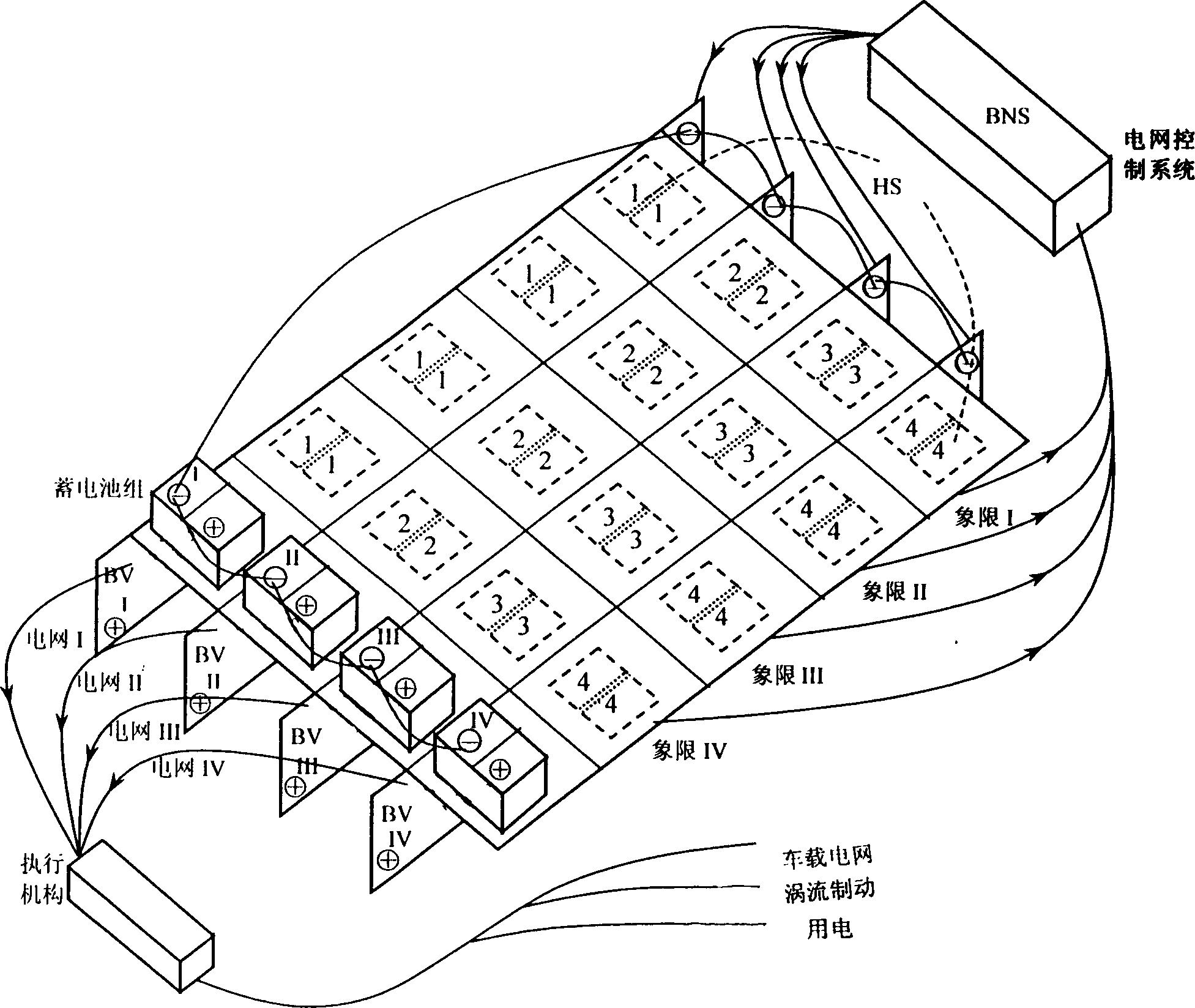
[0027] See figure 2 As shown, the vehicle power grid of the present invention includes a linear generator LG, a step-up chopper HS, a power distributor BV and a power grid control system BNS. The induced electromotive force of the linear generator LG rises with the speed of the train. Therefore, it must be matched with the step-up chopper HS before the power can be input into the vehicle power grid with a constant voltage (eg 440V). Each carriage of a maglev train is generally equipped with 32 step-up choppers HS directly connected to the linear generator LG, and the above-mentioned step-up choppers HS directly connected to the linear generator LG are divided into four quadrants I -IV, the choppers HS in each quadrant I-IV are divided into four groups of 1, 2, 3, and 4, and the choppers HS of the same group number in each column are connected to form four columns, and each column is connected to a Corresponding distributors BVI-IV are connected to form four sets of power gri...


PUM


Abstract

The power supply method for train power network on magnetic suspension train without power tracks features that the rechargeable accumulator pack powers the power network load on the train under the control of power network controller based on chaotic control policy via the power network distributor during cutoff, startup and emergency braking; the accumulator pack together with the linear power generator on the train powers the power network load on the train in low speed section; and the linear power generator on the train powers the power network load on the train while the stepup chopper of the power network on the train power the accumulator pack to ensure the 70-90 % rated capacity in high speed section. The present invention solves the technological problem for the accumulator pack in the train to power the power network on the trani without auxiliary power supply tracks.

Description

Technical field: [0001] The invention belongs to vehicle power supply, in particular to a power supply method for a vehicle-mounted power grid of a maglev train without a power supply rail and the configuration of the vehicle-mounted power grid. Background technique: [0002] As a new type of high-speed rail transit concept, the maglev train is still in the experimental operation stage in developed countries since it was proposed in the last century, and has not yet been officially put into commercial operation. One of the important reasons for this situation is that many technical measures of maglev trains are limited by the current high-tech integrated production level, resulting in excessive investment and lack of economy. For example, the current maglev train uses power supply rails and current receivers to provide auxiliary power supply to the vehicle power grid is an example. Unlike electric locomotives that obtain traction and power from the overhead catenary, maglev...

Claims


Application Information

Patent Timeline
Patent Type & Authority Applications(China)
IPC IPC(8): B60L1/00
Inventor 吴祥明钱梓文林国斌王凤鸣
Owner TONGJI UNIV
Why Eureka
Try Eureka