Voltage blocked diaphragm and producing method thereof

A technology of voltage clamping and diaphragm, which is applied in the direction of circuits, electrical components, battery pack components, etc.

Inactive Publication Date: 2005-04-27
WUHAN UNIV
View PDF0 Cites 11 Cited by
  • Summary
  • Abstract
  • Description
  • Claims
  • Application Information

AI Technical Summary

Problems solved by technology

[0004] The present invention proposes a voltage-clamping diaphragm and a preparation method thereof, the purpose of which is to establish an overcharg

Method used


Image

  • Voltage blocked diaphragm and producing method thereof
  • Voltage blocked diaphragm and producing method thereof

Examples


Embodiment Construction

[0017] specific implementation

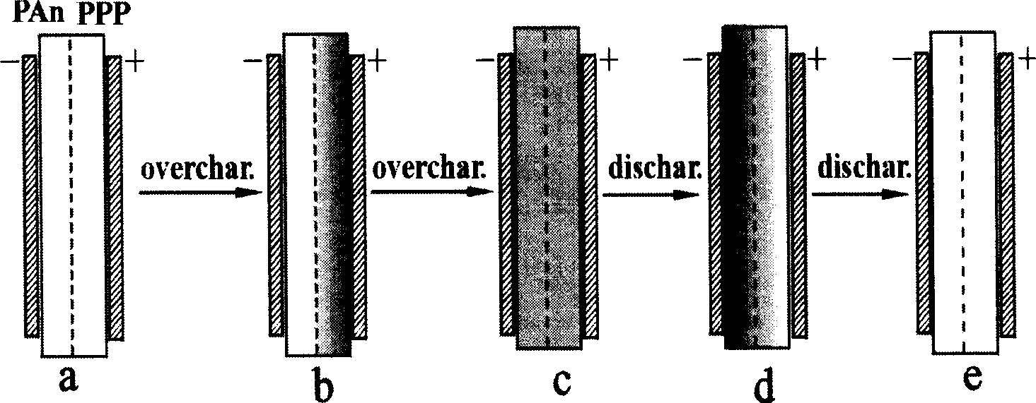
[0018] Application examples. Using polyaniline (PAn) and polyphenylene (PPP) as electroactive polymer materials on the negative side and positive side of the separator, nano-SiO 2 Powder is an inert component additive, polytetrafluoroethylene (PTFE) emulsion is a binder, and rolls are used to make films with a thickness of about 25 μm, and then the two films are laminated and integrated by hot pressing. With this integrated PPP / PAn composite film as a separator, LiCoO 2 as positive electrode, Li sheet as negative electrode, 1mol / L LiPF 6 The / EC+DMC solution was used as the electrolyte to assemble the experimental lithium battery. In the assembled battery, the PPP side of the composite film is next to the LiMn 2 o 4 electrode, while the PAn face is next to the Li electrode.

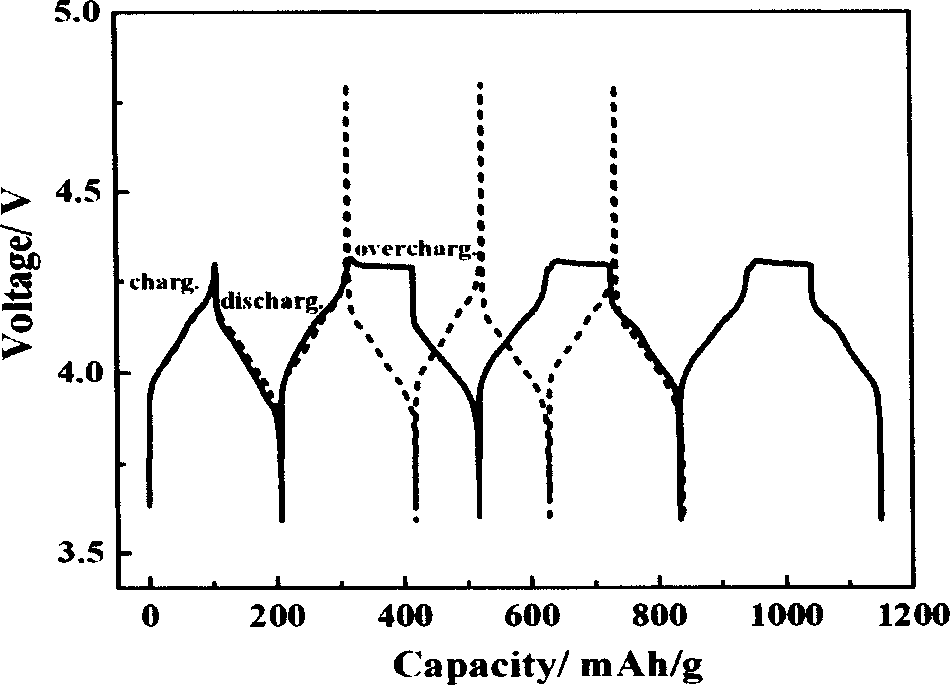
[0019] figure 1 Comparing Li / LiMn with conventional polypropylene separator and PPP / PAn composite film 2 o 4 The charging and discharg...


PUM


Abstract

The present invention is voltage clamping diaphragm and its preparation process. The diaphragm is formed via superposing two layers of porous electrically active polymer film, including the layer near the negative pole of porous electrically active polymer film capable of generating p-doping only and incapable of generating n-doping, and the layer near the positive pole of porous electrically active polymer film with relatively high oxidation potential. All the polymer materials in use are electrical insulator in intrinsic state and excellent electronic conductor in P-doped state. The diaphragm may be used to provide reversible inside overcharge protection for secondary battery.

Description

technical field [0001] The invention relates to the composition principle of a voltage clamping diaphragm and belongs to the field of chemical power sources. Background technique [0002] The safety of the battery in the overcharged state has always been the biggest application problem faced by the organic electrolyte secondary battery. For an aqueous solution secondary battery, when it is in an overcharged state, water is oxidized at the positive electrode of the battery to generate oxygen, and reduced at the negative electrode to generate hydrogen, and the resulting gas product can reversibly recombine into water inside the battery. This reversible decomposition-recombination of water provides an internal overcharge protection mechanism for the aqueous solution secondary battery, so that the aqueous solution secondary battery has good overcharge resistance. For non-aqueous secondary battery systems using organic electrolyte solutions, the batt...

Claims


Application Information

Patent Timeline
IPC IPC(8): C08J5/22C08J9/00H01M2/16H01M2/34
CPCY02E60/12Y02E60/10
Inventor 艾新平肖利芬杨汉西曹余良
Owner WUHAN UNIV
Why Eureka
Try Eureka