Plasma processing device and plasma processing method

A plasma and processing device technology, which is applied in the fields of plasma, semiconductor/solid-state device manufacturing, coating, etc., can solve the problems of poor thermal protection film plasma processing and high plasma temperature, and achieves improved plasma processing performance and increased plasma temperature. The effect of high plasma density and cost reduction

Inactive Publication Date: 2005-04-27
MATSUSHITA ELECTRIC WORKS LTD +1
View PDF1 Cites 22 Cited by
  • Summary
  • Abstract
  • Description
  • Claims
  • Application Information

AI Technical Summary

Problems solved by technology

[0009] However, the problem is that when the frequency is increased to the high frequency region, such as 13.56MHz, the plasma temperature will be higher
As a result, the above-mentioned plasma processing apparatus cannot be used for plasma processing thin films with poor thermal protection since the object to be processed is thermally damaged by the heat of the plasma

Method used


Image

  • Plasma processing device and plasma processing method
  • Plasma processing device and plasma processing method
  • Plasma processing device and plasma processing method

Examples


example 1-5

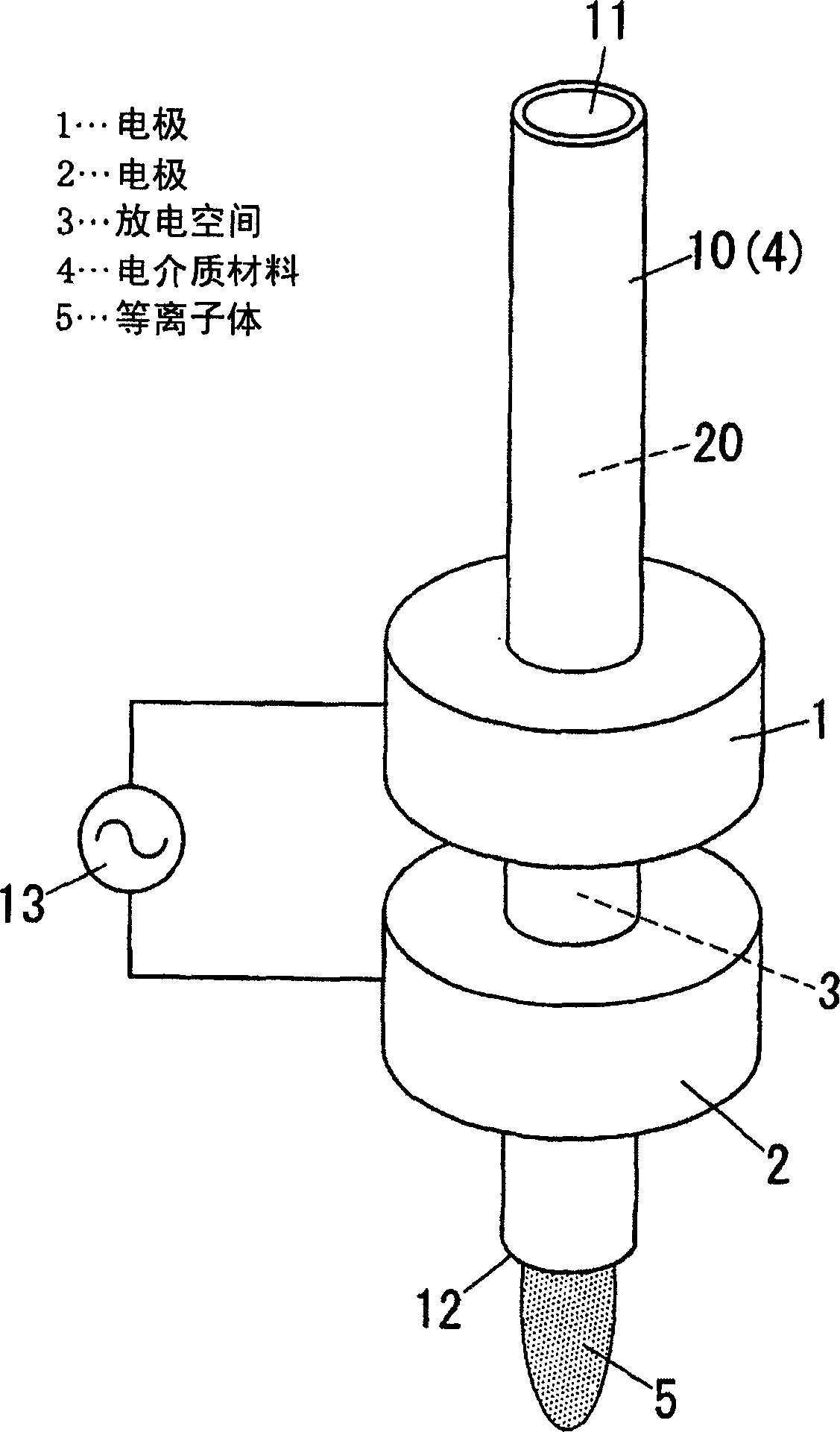
[0164] use as Figure 16 The plasma treatment apparatus shown is for spot treatment. The reactor 10 of the plasma processing apparatus was made of a quartz tube having an inner diameter of 3 mm and an outer diameter of 5 mm, which had a hollow flange portion 6 (storage area 15) having an outer diameter of 50 mm. The electrodes 1, 2 and the flange portion 6 are arranged to have as Figure 17 The cross-sectional structure shown in .

[0165] A plasma generating gas is supplied from an inlet 11 of the reactor 10 to the gas flow channel 20, and plasma is generated by a voltage supplied from a power source 13 connected to the electrode 1 on the upstream side and the electrode 1 on the downstream side. Electrode 2. Plasma 5 emerges from outlet 12 . Plasma treatment is achieved by exposing the object on the downstream side of the outlet 12 to the plasma. A mixture of argon and oxygen was used as the plasma generation gas. Other conditions for generating plasma are shown in Tabl...

example 11

[0203] use as Figure 18 The plasma treatment apparatus shown is for spot treatment. The reactor 10 of this apparatus was obtained by forming a conical nozzle portion 14 with an outlet 12 having an inner diameter of 1 mm on the lower side of the reactor 10 of Examples 1 to 5. Other structures are basically the same as examples 1 to 5. Plasma 5 was generated under the plasma generation conditions shown in Table 4. As in the case of Examples 1 to 5, evaluation was performed.

example 12

[0205] use as Figure 15 The plasma treatment apparatus shown is for spot treatment. The reactor 10 of this apparatus was obtained by forming a conical nozzle portion 14 with an outlet 12 having an inner diameter of 1 mm on the lower side of the reactor 10 of Comparative Examples 1 and 2. Other structures are basically the same as examples 1 to 5. Plasma 5 was generated under the plasma generation conditions shown in Table 4. As in the case of Examples 1 to 5, evaluation was performed. The above evaluation results are shown in Table 4.

[0206] Example 11

[0207] It is apparent from Table 4 that, compared with Example 4, the flow rate of plasma 5 increases due to the narrowing of the outlet 12 of the reactor 10, so that equivalent performance. However, when the voltage applied between the electrodes 1, 2 is increased to improve the plasma performance, as in Figure 12 In the reactor shown without the flange portion 6, a back discharge occurs outside the re...


PUM

PropertyMeasurementUnit
thicknessaaaaaaaaaa
lengthaaaaaaaaaa

Abstract

A plasma treatment apparatus and method are provided, which have the capability of maintaining a stable discharge, achieving a sufficient plasma treatment, and reducing plasma temperature. In this apparatus, electrodes are arranged to define a discharge space therebetween, and a dielectric material is disposed at a discharge-space side of at least one of the electrodes. A voltage is applied between the electrodes, while a plasma generation gas being supplied into the discharge space, to develop the discharge in the discharge space under a pressure substantially equal to atmospheric pressure, and provide the plasma generated by the discharge from the discharge space. A waveform of the voltage applied between the electrodes is an alternating voltage waveform without rest period. At least one of rising and falling times of the alternating voltage waveform is 100 mu sec or less. A repetition frequency is in a range of 0.5 to 1000 kHz. An electric-field intensity applied between the electrodes is in a range of 0.5 to 200 kV / cm.

Description

technical field [0001] The invention relates to a plasma treatment device and a plasma treatment method using the device, which can be used to clean impurities on the surface of an object to be treated such as organic materials, etch or peel off protective materials, improve the adhesion of organic films, reduce Metal oxides, film formation, pretreatment for plating or coating, and surface treatment such as surface modification of various materials or parts, and are particularly preferably applied to Surface cleaning of electronic components requiring precise connections. Background technique [0002] In the past, plasma treatment such as surface modification was performed on an object to be treated by defining a discharge space between a pair of opposed electrodes; while supplying a plasma generating gas into the discharge space, applying a voltage to generate a discharge in the discharge space to obtain plasma; and eject the plasma or active species of the plasma from the...

Claims


Application Information

Patent Timeline
Patent Type & Authority Applications(China)
IPC IPC(8): H05H1/24
CPCH05H2001/2412H05H1/24H05H2245/123H05H1/2406H05H1/2465H05H2245/40
Inventor 田口典幸泽田康志松永浩一
Owner MATSUSHITA ELECTRIC WORKS LTD
Why Eureka
Try Eureka