Efficient ultrasonic working apparatus

A processing equipment, ultrasonic technology, applied in the field of high-efficiency ultrasonic processing equipment, can solve problems such as unsatisfactory surface quality and large tool wear

Inactive Publication Date: 2005-05-04
SHANDONG HUAWIN ELECTRICAL & MECHANICAL TECH
View PDF0 Cites 22 Cited by
  • Summary
  • Abstract
  • Description
  • Claims
  • Application Information

AI Technical Summary

Problems solved by technology

In this case, not only the tool wear is hig

Method used


Image

  • Efficient ultrasonic working apparatus
  • Efficient ultrasonic working apparatus
  • Efficient ultrasonic working apparatus

Examples


Embodiment Construction

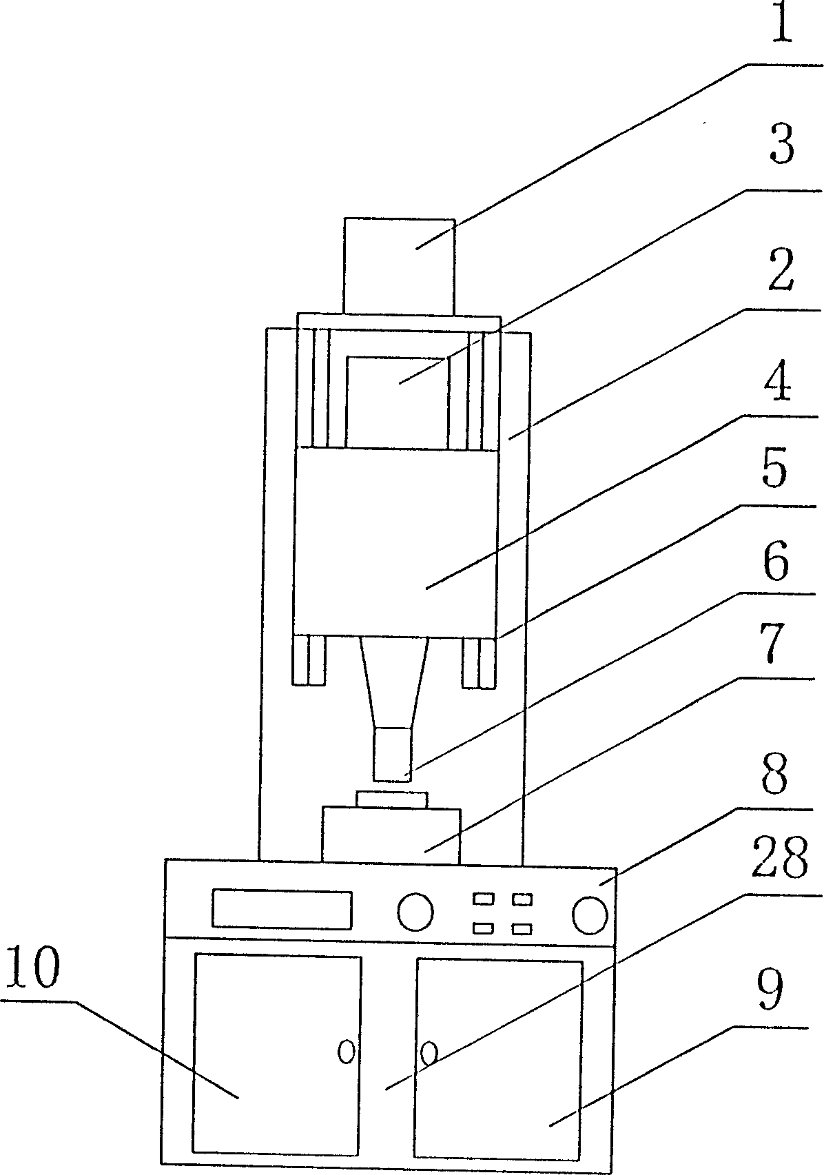
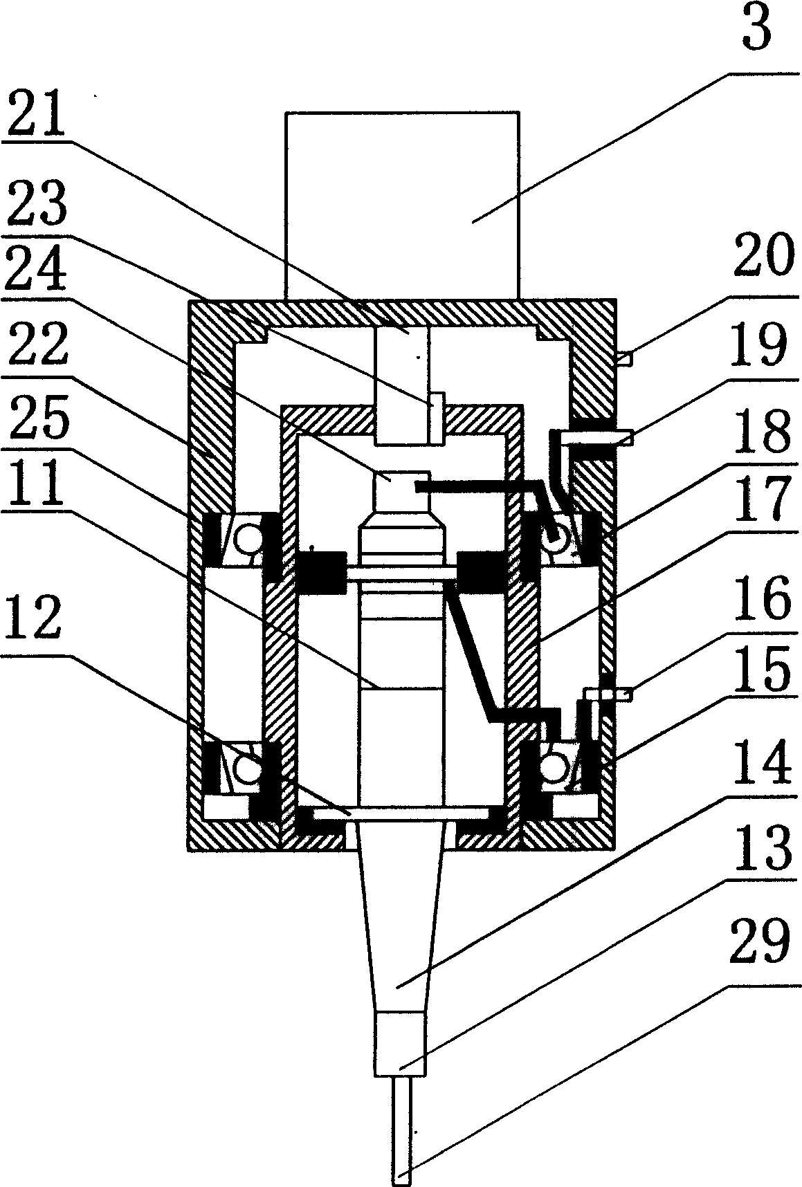
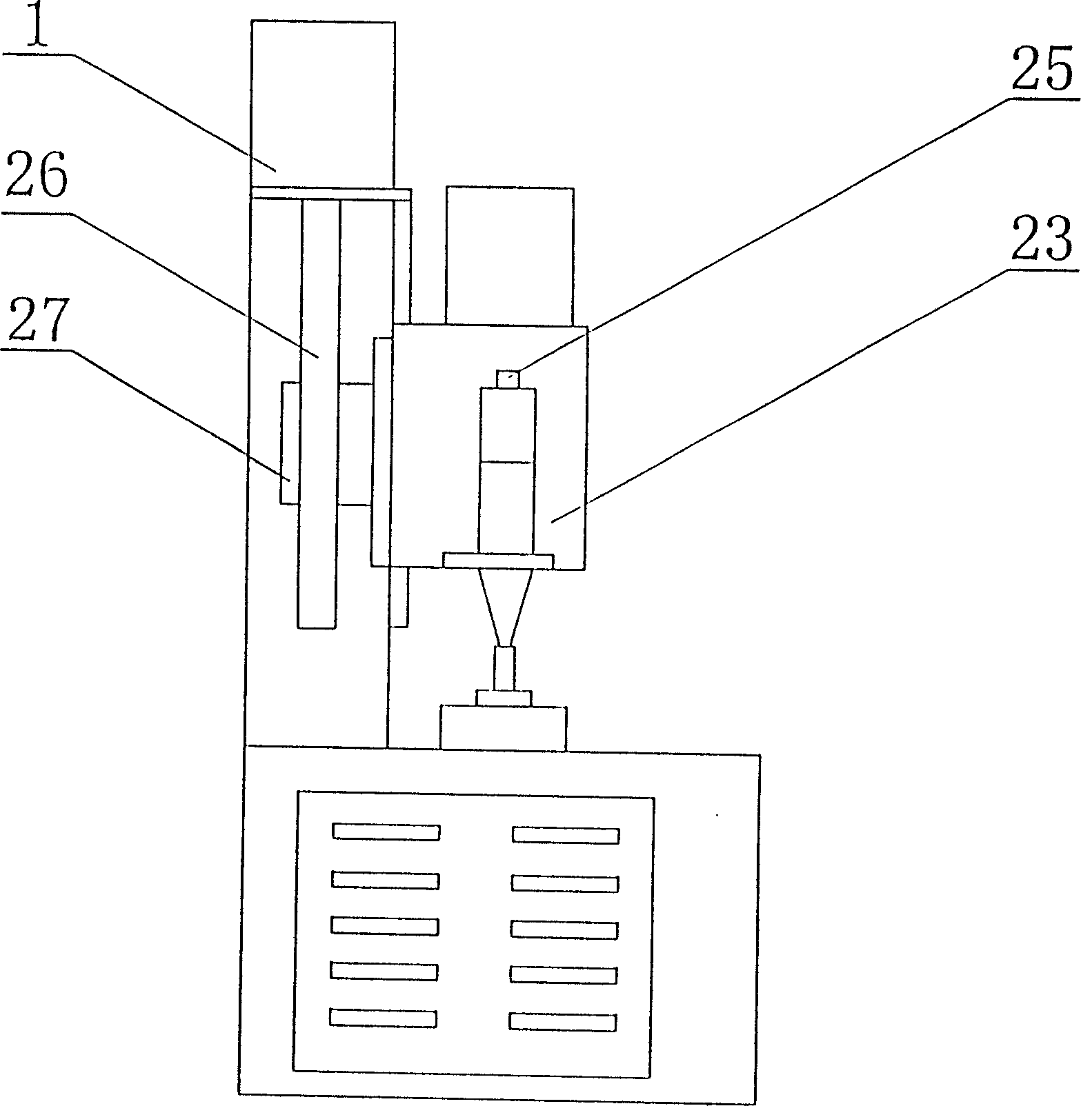
[0012] Attached below figure 1 , 2 , 3 A high-efficiency ultrasonic processing equipment of the present invention is described in detail below.

[0013] as attached figure 1 , 2 , 3, a high-efficiency ultrasonic processing equipment is composed of a base 8, a bed 2, a guide rail 5, an ultrasonic vibration working device 4, a workbench 7, a spindle feed device 10, a control device 9 and an ultrasonic generator 28. The bed 2 is set on the base 8, and the guide rail 5 is set on the bed 2 in parallel. The ultrasonic vibration working device 4 moves up and down along the guide rail 5 through the supporting plate 27 of the spindle feeding device 10, and the workbench 7 is set on the ultrasonic vibration working device. 4, the control device 9 is arranged in the inner cavity of the base 8 and communicates with the spindle feeding servo motor 1 of the spindle feeding device 10, the sensor 24 and the transducer 11 of the ultrasonic vibration working device 4 through wires. connecte...


PUM


Abstract

The present invention provides a high-effective ultrasonic processing equipment. Its structure is formed base, machine body, guideways, ultrasonic vibration working device, working table, main shaft feeding device, control device and ultrasonic generator. The machine body is placed on the base, said guide ways are parallelly placed on the machine body, the ultrasonic vibration working device is connected with guideways and can be up-down moved along the guideways by means of supporting plate of main shaft feeding device, the working table is placed on the base under the ultrasonic vibration working device, the control device is placed in the internal cavity of the base and is connected with main shaft feeding servo-actuator and sensor and energy converter of ultrasonic vibration working device by means of wires and can be formed into a closed-loop control circuit, and the ultrasonic generator is placed in the internal cavity of base and is connected with energy converter by means of wire.

Description

1. Technical field [0001] The invention relates to a cutting machine tool, in particular to a high-efficiency ultrasonic processing equipment for processing hard and brittle materials. 2. Technical background [0002] Nowadays, in the fields of medical equipment, optical industry, machinery, communication, electronics, energy and automobile industry, the demand for high hardness parts is increasing day by day. However, such materials have the characteristics of high hardness, high brittleness and difficult processing, and it is difficult to carry out precise forming processing on these materials. The traditional processing method is very inefficient in the process of processing and finishing, because most of these materials are non-conductors and are not the object of electric processing technology. The use of laser processing technology will cause thermal damage and micro cracks to the material. In the existing cutting methods, some materials have to work for a long time ...

Claims


Application Information

Patent Timeline
IPC IPC(8): B06B1/02B23B27/00
Inventor 郝俊山赵显华
Owner SHANDONG HUAWIN ELECTRICAL & MECHANICAL TECH
Why Eureka
Try Eureka