Timing recovering method

A timing recovery and timing error technology, applied in baseband systems, digital transmission systems, electrical components, etc., to solve the problems that the timing recovery system cannot work normally and the capture range is not large enough.

Active Publication Date: 2005-05-11
HANGZHOU NATCHIP SCI & TECH
View PDF1 Cites 4 Cited by
  • Summary
  • Abstract
  • Description
  • Claims
  • Application Information

AI Technical Summary

Problems solved by technology

In this method, it is necessary to calculate a certain value according to the relationship between the fixed sampling clock frequency and the transmitter symbol rate and put it into the standard delay register. When there is a large error in the fixed sampling clock frequency

Method used


Image

  • Timing recovering method
  • Timing recovering method
  • Timing recovering method

Examples


Embodiment Construction

[0015] Here, the QPSK modulation method is used as an example to illustrate the effectiveness and specific implementation methods of the timing recovery method of the present invention, but the timing recovery method of the present invention is equally applicable to MPSK and APSK modulation modes such as BPSK, 8PSK, 16APSK, and 32APSK.

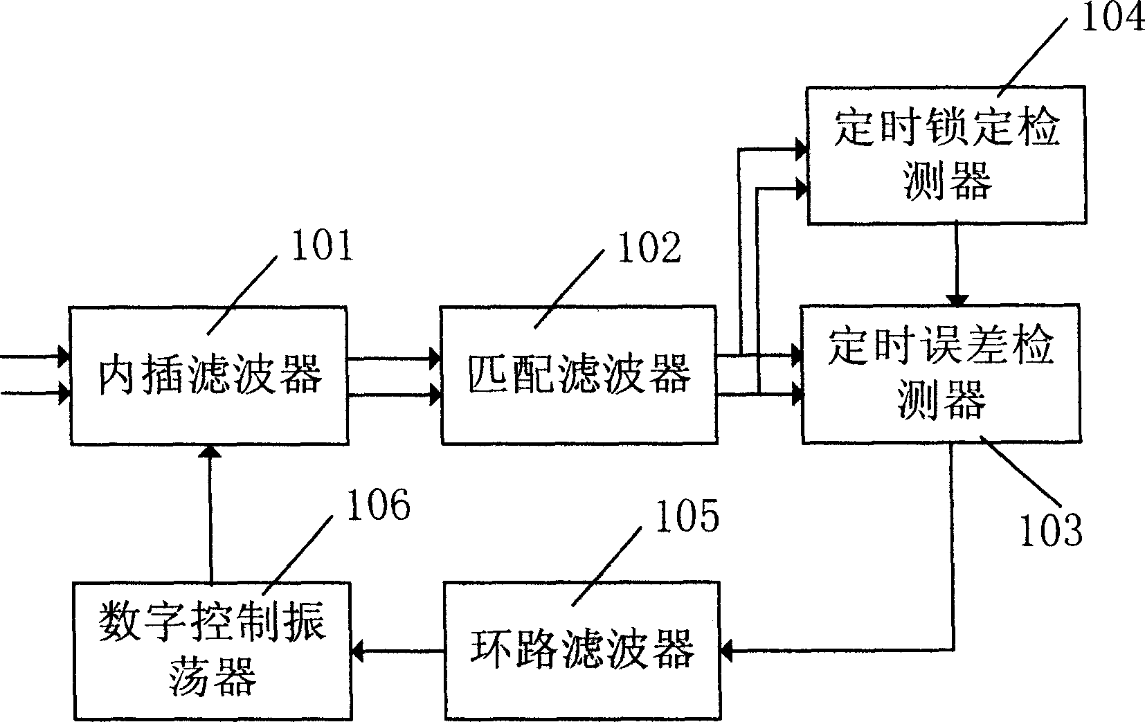
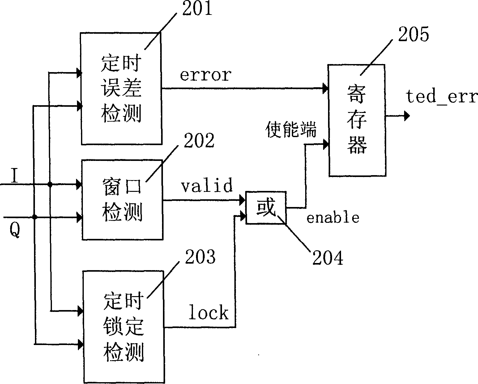
[0016] Such as figure 1 As shown, the timing recovery method of this embodiment is that the interpolation filter 101 performs symbol-synchronous sampling on the received QPSK signal, the matched filter 102 matches the shaping filter of the transmitter, and the timing error detector 103 calculates the difference between the sampling samples. Between the effective timing error, the lock detector 104 provides an indication signal whether the timing is locked, the loop filter 105 filters the effective timing error output by the timing error detector, and the digitally controlled oscillator 106 provides the interpolation filter integer and fraction ...


PUM


Abstract

The method includes following steps: the timing error is exacted and inputted; if the locking detector indicates the timing is locking, then the widows detecting is not made; the timing errors of inputted signal extracted at each time are all outputted to loop filter; if the locking detector indicates the timing is not locking, then the timing error will be decided if it is available according to the result of windows detecting.

Description

technical field [0001] The invention belongs to the field of digital signal processing, in particular to a timing recovery method in a digital signal receiver. Background technique [0002] Timing recovery is required in a digital receiver using the received signal, a method of synchronizing the receiver clock with the transmitter clock by which the received signal is sampled at the optimal point in time . [0003] The invention patent with the application number 97102528.2 discloses a timing recovery method in a digital receiver, which allows the system to sample and work with a clock greater than twice the maximum symbol rate, and realize synchronization of signals with different symbol rates with a fixed frequency clock . In this method, it is necessary to calculate a certain value according to the relationship between the fixed sampling clock frequency and the transmitter symbol rate and put it into the standard delay register. When there is a l...

Claims


Application Information

Patent Timeline
IPC IPC(8): H04L25/04H04L25/17
Inventor 黄智杰庞智博张明
Owner HANGZHOU NATCHIP SCI & TECH
Why Eureka
Try Eureka