Elactro magnetic commutator

A commutator, electromagnet technology, applied in the direction of components with teeth, belts/chains/gears, mechanical equipment, etc., can solve problems such as infeasibility, and achieve the effects of convenient operation, flexible commutation, and smooth transmission

Inactive Publication Date: 2005-06-08
DALIAN UNIV
View PDF0 Cites 2 Cited by
  • Summary
  • Abstract
  • Description
  • Claims
  • Application Information

AI Technical Summary

Problems solved by technology

For a power source such as an internal combustion engine, which is only one direction of rotation, this method is not feasible

Method used


Image

  • Elactro magnetic commutator

Examples


Embodiment Construction

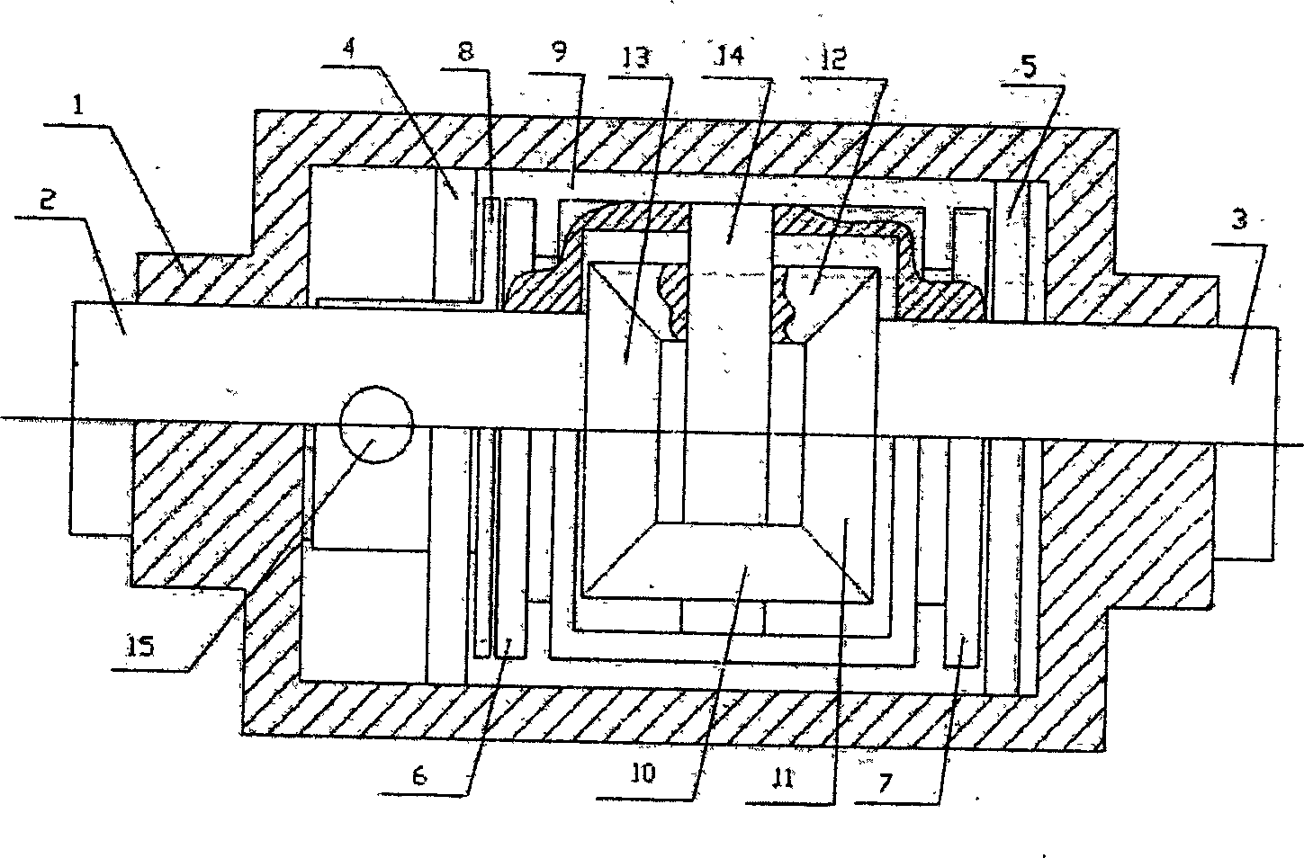
[0010] As shown in the figure, the commutation principle and working state of the electromagnetic commutator are as follows: when rotating in the same direction, the input shaft 2 is connected to the power source. The electromagnet 4 is energized to make the friction plate 8 of the input shaft and the left end friction plate 6 of the commutator 9 rotate synchronously through the connection of electromagnetic force, so that the same direction rotation of the input shaft and the output shaft is realized. When rotating in the opposite direction, the electromagnet 5 is energized, and the electromagnet 4 is de-energized simultaneously, and the friction plate 7 at the right end of the commutator housing 9 then remains fixed with the housing 1 due to electromagnetic force. At this time, the input shaft still drives the bevel gear train to move, because the bevel gear 10 and the bevel gear 12 are installed on the commutator housing 9 through the bevel gear fixed shaft 14, and are loope...


PUM


Abstract

A electromagnetism commutator., which involves the combining of the axis. It includes the cover, the transferring axis and the electromagnet, the two-sides grating pieces which contains the cover of the commutator. The in and out transferring axis is connected with the active gear and the passive gear. When it galvanizes, the transferring-in axis will run synchronically. Or it will work contrarily.

Description

technical field [0001] The present invention relates to the coupling of shafts in mechanical transmission, in particular to commutator components for changing the transmission direction. Background technique [0002] At present, in the field of mechanical transmission, most of them use gear transmission. When it is necessary to change the direction of rotation of the output shaft, there are two main methods. One is to change the output direction by changing the way the gears mesh. Tooth phenomenon, ranging from wearing out the gears, to breaking the gears and making them unusable. The second is by changing the rotation direction of the power source, which requires that the power source must be in both forward and reverse rotation states. For a power source such as an internal combustion engine, which is only one direction of rotation, this method is not feasible. Contents of the invention [0003] The purpose of the present invention is to provide an electromagnetic comm...

Claims


Application Information

Patent Timeline
Patent Type & Authority Applications(China)
IPC IPC(8): F16H61/00F16H63/00
Inventor 周磊
Owner DALIAN UNIV
Why Eureka
Try Eureka