Rotary device for regulating flow of spray head

A flow adjustment device, a rotary technology, applied in the field of nozzle flow adjustment devices to adjust the flow of nozzles, can solve the problems of time and manpower

Inactive Publication Date: 2005-07-06
SEMICON MFG INT (SHANGHAI) CORP +1
View PDF0 Cites 14 Cited by
  • Summary
  • Abstract
  • Description
  • Claims
  • Application Information

AI Technical Summary

Problems solved by technology

[0002] In the semiconductor industry, wafer processing uniformity is very important, and in order to achieve the best wafer processing uniformity, many process parameters are usually changed, especially when the wafer (Wafer) undergoes chemical vapor deposition (CVD) ), plasma-assisted chemical vapor deposition (PECVD), etching (etch) and other processes, the gas is usually ejected through the nozzle and reacts with the surface of the wafer, and b

Method used


Image

  • Rotary device for regulating flow of spray head
  • Rotary device for regulating flow of spray head
  • Rotary device for regulating flow of spray head

Examples


Embodiment Construction

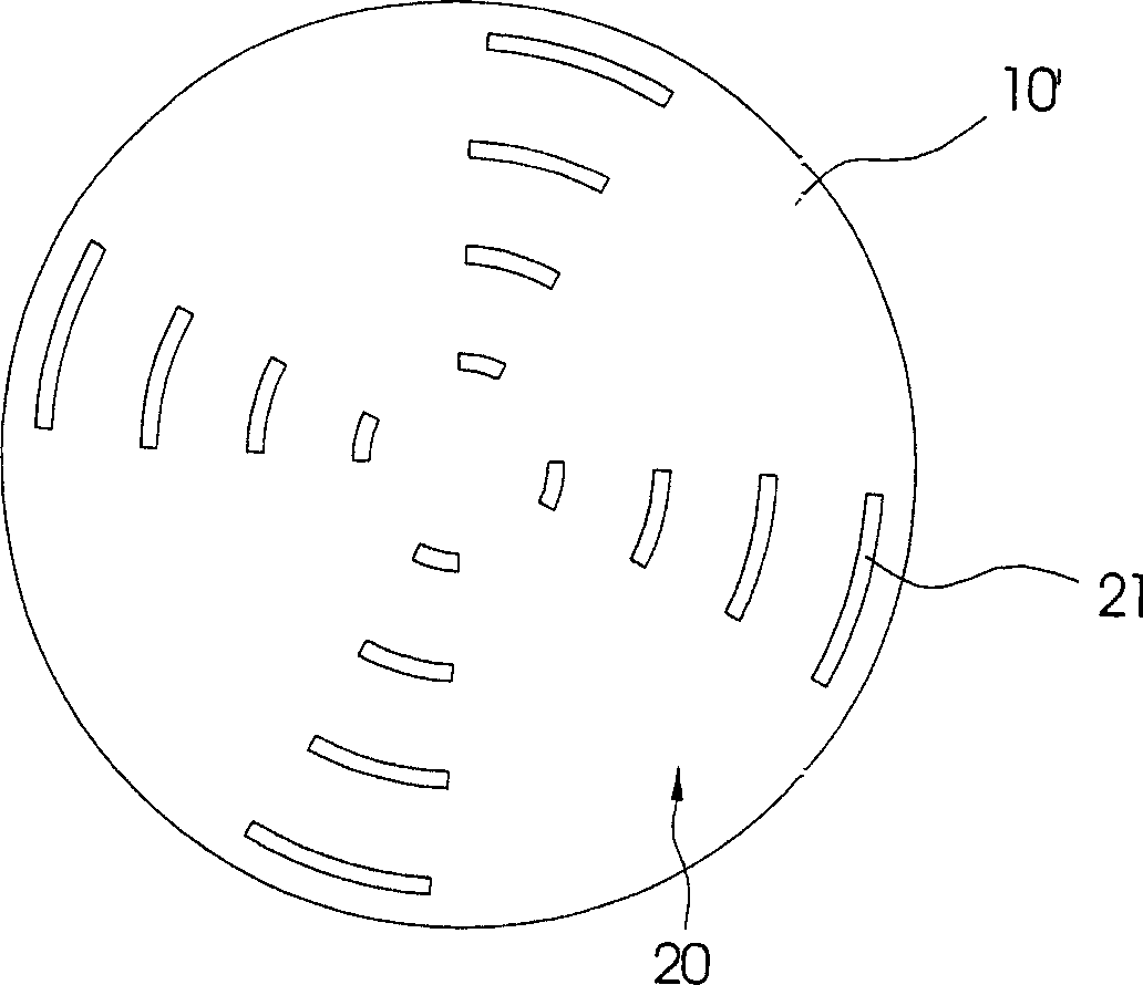
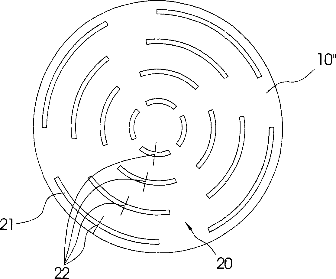
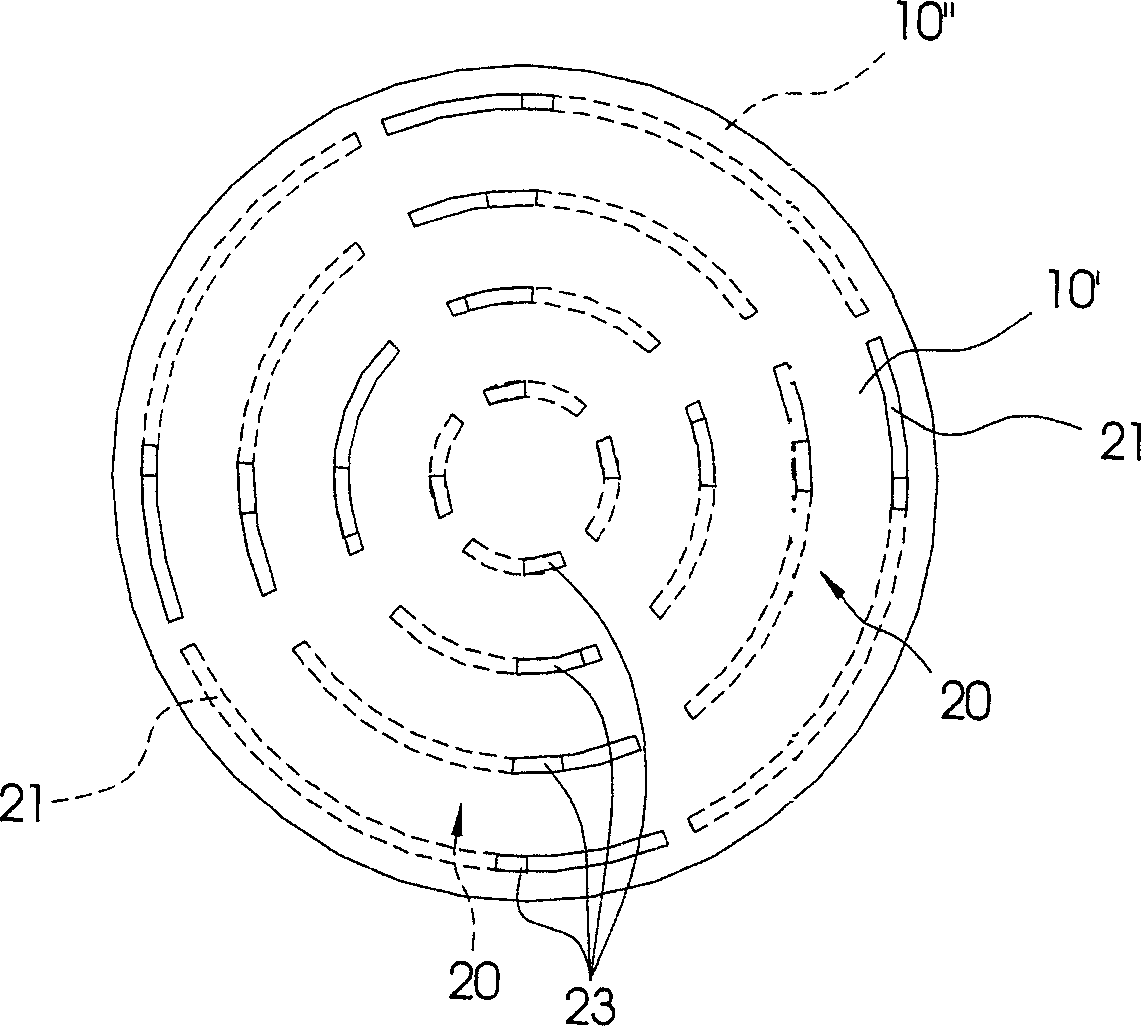
[0019] see Figure 1 to Figure 4 Shown, the present invention is a kind of rotary sprinkler head flow adjustment device, and it comprises two disc bodies 10 and several piercing groove groups 20 on it, and two disk bodies 10 are piled up together, and described piercing groove group 20 are arranged oppositely on the disc body 10 respectively, and the disc body 10 is assembled on a shower head, and the outlet of the shower head is communicated with the through-groove group 20, and through the disc body 10 is relatively rotated to control the size of the communication area of ​​the opposite through-groove group 20, so as to control the flow rate of the fluid flowing out of the spray head through the connected through-groove group 20.

[0020] see figure 1 and figure 2 As shown, there are four through-groove groups 20 which respectively have four concentric arc-shaped through-grooves 21, and are arranged on the disc body 10 with different radii. Please refer to figure 1 As sh...


PUM


Abstract

This invention relates to rotary spray flow adjusting device, which comprises at least two round discs and several relative groove sets, wherein the said two round discs are overlapped together and the groove sets are separately formed on the round discs located on the spray head. The groove sets are connected to the exit mouth of the spray to control the groove connection area and to control flow volume through the spray.

Description

technical field [0001] The invention relates to a rotary nozzle flow adjustment device, especially a nozzle flow adjustment device suitable for adjusting the nozzle flow. Background technique [0002] In the semiconductor industry, wafer processing uniformity is very important, and in order to achieve the best wafer processing uniformity, many process parameters are usually changed, especially when the wafer (Wafer) undergoes chemical vapor deposition (CVD) ), plasma-assisted chemical vapor deposition (PECVD), etching (etch) and other processes, the gas is usually ejected through the nozzle and reacts with the surface of the wafer, and by changing the gas flow rate, pressure, temperature of the nozzle In order to achieve the processing uniformity of the wafer, and in the processing process, it is often necessary to change various processing parameters in order to meet the requirements of wafer uniformity, so it takes a lot of time and manpower, but using this method to chang...

Claims


Application Information

Patent Timeline
IPC IPC(8): B05B1/30B05B3/08
Inventor 吴汉明
Owner SEMICON MFG INT (SHANGHAI) CORP
Why Eureka
Try Eureka