Exhaust apparatus for small-sized engine

An exhaust device and engine technology, which is applied to exhaust devices, engine components, machines/engines, etc., can solve problems such as inability to achieve exhaust noise, reduction, and narrowing of exhaust passages 241.

Active Publication Date: 2005-07-13
HONDA MOTOR CO LTD
View PDF1 Cites 18 Cited by
  • Summary
  • Abstract
  • Description
  • Claims
  • Application Information

AI Technical Summary

Problems solved by technology

Therefore, it is impractical to narrow the exhaust passage 241 or further reduce the number of exhaust holes 242 to further reduce the exhaust noise.
If the exhaust passage 241 is widened or the number of exhaust holes 242 is increased, the back pressure can be reduced, thereby preventing the muffler 233 from being overheated, but sufficient reduction in exhaust noise cannot be achieved

Method used


Image

  • Exhaust apparatus for small-sized engine
  • Exhaust apparatus for small-sized engine
  • Exhaust apparatus for small-sized engine

Examples


Embodiment Construction

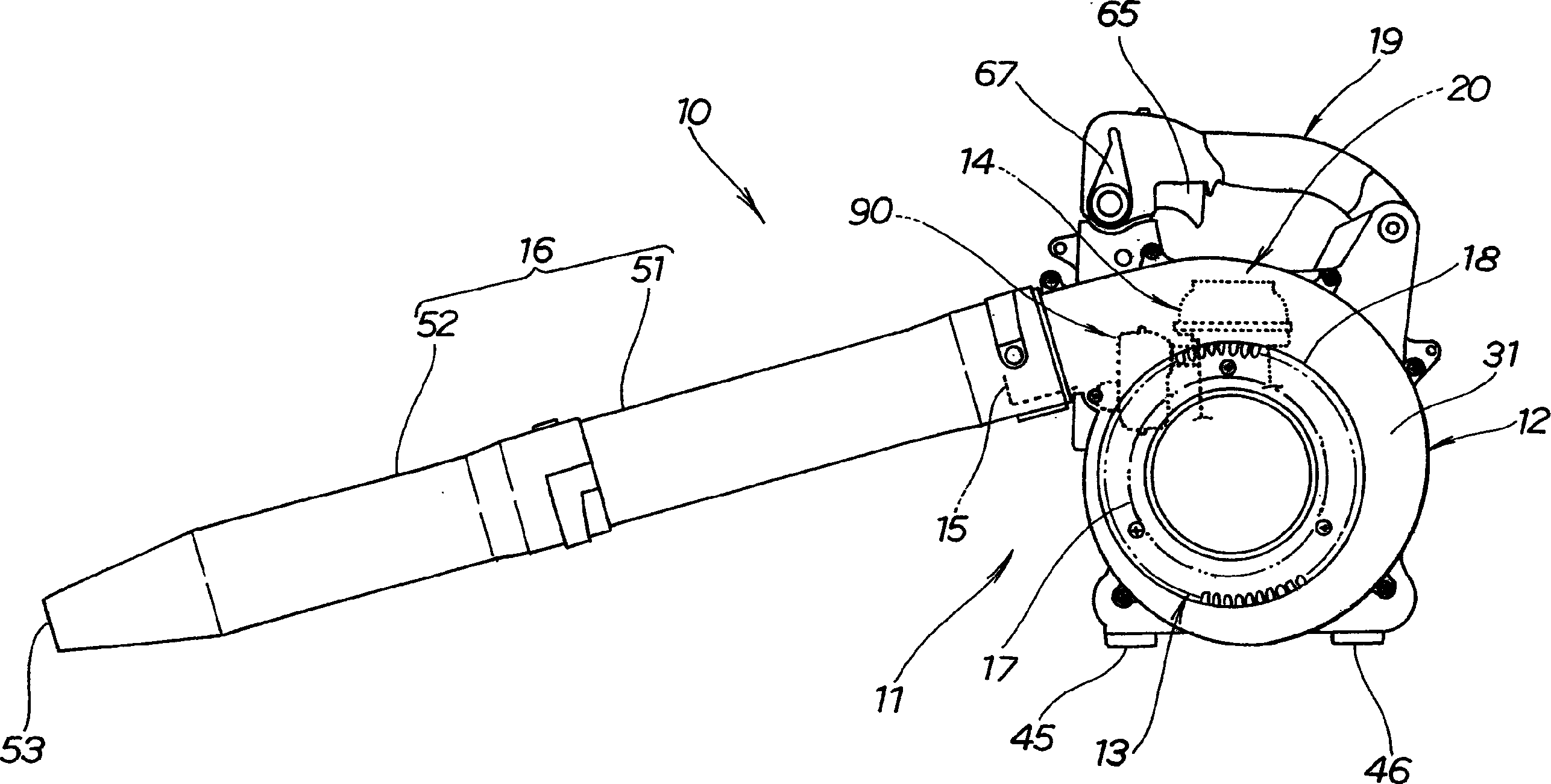
[0025] Such as figure 1 2, the portable fan unit 10 employs an exhaust 90 for a small engine (hereinafter "engine") 14 according to one embodiment of the present invention.

[0026] refer to figure 1 , the portable fan unit 10 includes a fan housing 12 containing a fan 13 therein, and a prime mover unit 20 mounted on the fan housing 12 for driving the fan 13 . A discharge duct 16 is installed on a discharge portion 15 formed in the fan case 12 for discharging air from the fan case 12 . A fan cover 18 is mounted on the intake portion of the fan case 12 . A main handle 19 is installed on the top of the fan casing 12 .

[0027] The portable fan unit 10 has a main body 11 including a fan housing 12 , a fan cover 18 and a main handle 19 .

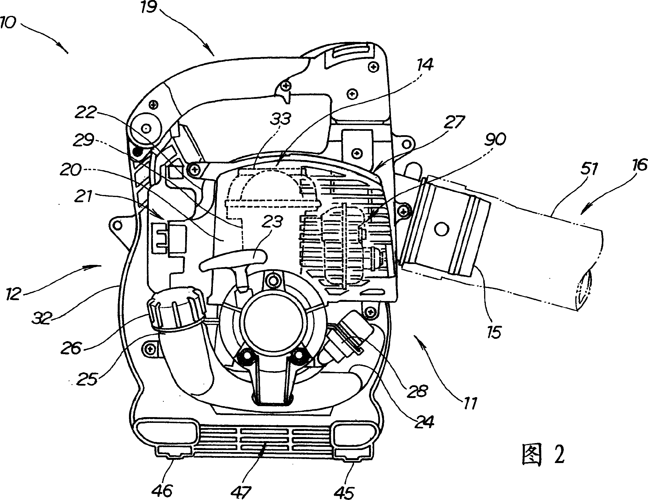
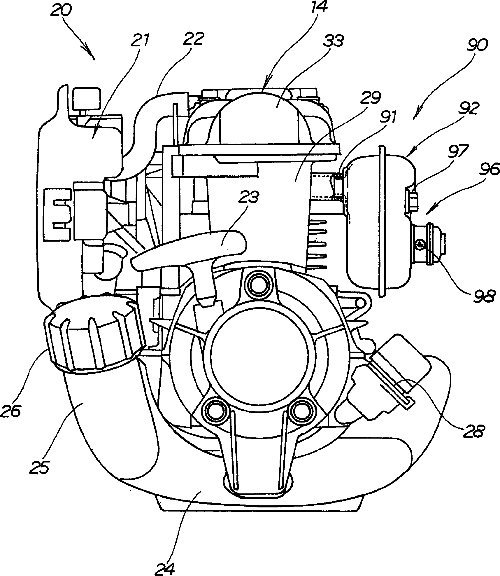
[0028] As shown in FIG. 2, the prime mover unit 20 is mounted on a right fan case 32 which will be described later. The prime mover cover 27 covers the engine 14 and the exhaust 90 of the prime mover unit 20 .

[0029] image 3 The prime ...


PUM


Abstract

An exhaust device (90) for a small engine (14) includes a muffler (92) having an exhaust section for exhausting exhaust gases from an exhaust pipe (91). A tubular member (121) is mounted on the exhaust portion of the muffler. Inside the tubular part, a filter (122) made of metal fibers is provided for reducing exhaust noise.

Description

technical field [0001] The present invention relates to an exhaust device for a small engine used as a power source for a portable working machine such as a blower or a lawnmower. Background technique [0002] An exhaust device disclosed in, for example, JP-A-11-13452 includes an exhaust pipe connected to a small engine and a box-shaped small muffler mounted on a distal end portion of the exhaust pipe. [0003] Fig. 11 of this specification shows the exhaust device disclosed in the above-mentioned document. In FIG. 11, reference numeral 230 denotes an exhaust device, which includes an exhaust pipe 232 extending from an engine 231, a box-shaped muffler 233 mounted on the exhaust pipe 232, and a A spark arrestor 234 that prevents sparks contained in the high temperature exhaust gas from entering the air. [0004] The muffler 233 includes a first expansion chamber 235 communicated with the exhaust pipe 232, a second expansion chamber 237 communicated with the first expansion ...

Claims


Application Information

Patent Timeline
Patent Type & Authority Applications(China)
IPC IPC(8): F01N1/24F01N1/04F01N1/08F01N1/10F01N3/06F01N13/08F01N13/18
CPCF01N1/04F01N1/082F01N1/089F01N1/10F01N13/002F01N2450/30F01N2490/08F01N2530/04F01N2590/06Y10S173/02F01N1/24
Inventor 那须野寿春石川武
Owner HONDA MOTOR CO LTD
Why Eureka
Try Eureka