Flat type fluorescent lamp

A fluorescent lamp and flat-panel technology, applied in the direction of fluorescent lamps, light sources, discharge lamps, etc., can solve problems such as brightness differences and weakened luminous efficiency

Inactive Publication Date: 2005-07-20
李桂承
View PDF0 Cites 2 Cited by
  • Summary
  • Abstract
  • Description
  • Claims
  • Application Information

AI Technical Summary

Problems solved by technology

However, since the purpose of generally setting the diffuser is to compensate for the uniformity by suppressing the light emission in the high-brightness area, the diffuser weakens the overall luminous efficiency
Therefore, due to the large amount of luminance differences in conventional flat fluorescent lamps, the use of diffusers to compensate for luminance has limitations

Method used


Image

  • Flat type fluorescent lamp
  • Flat type fluorescent lamp
  • Flat type fluorescent lamp

Examples


Embodiment 1

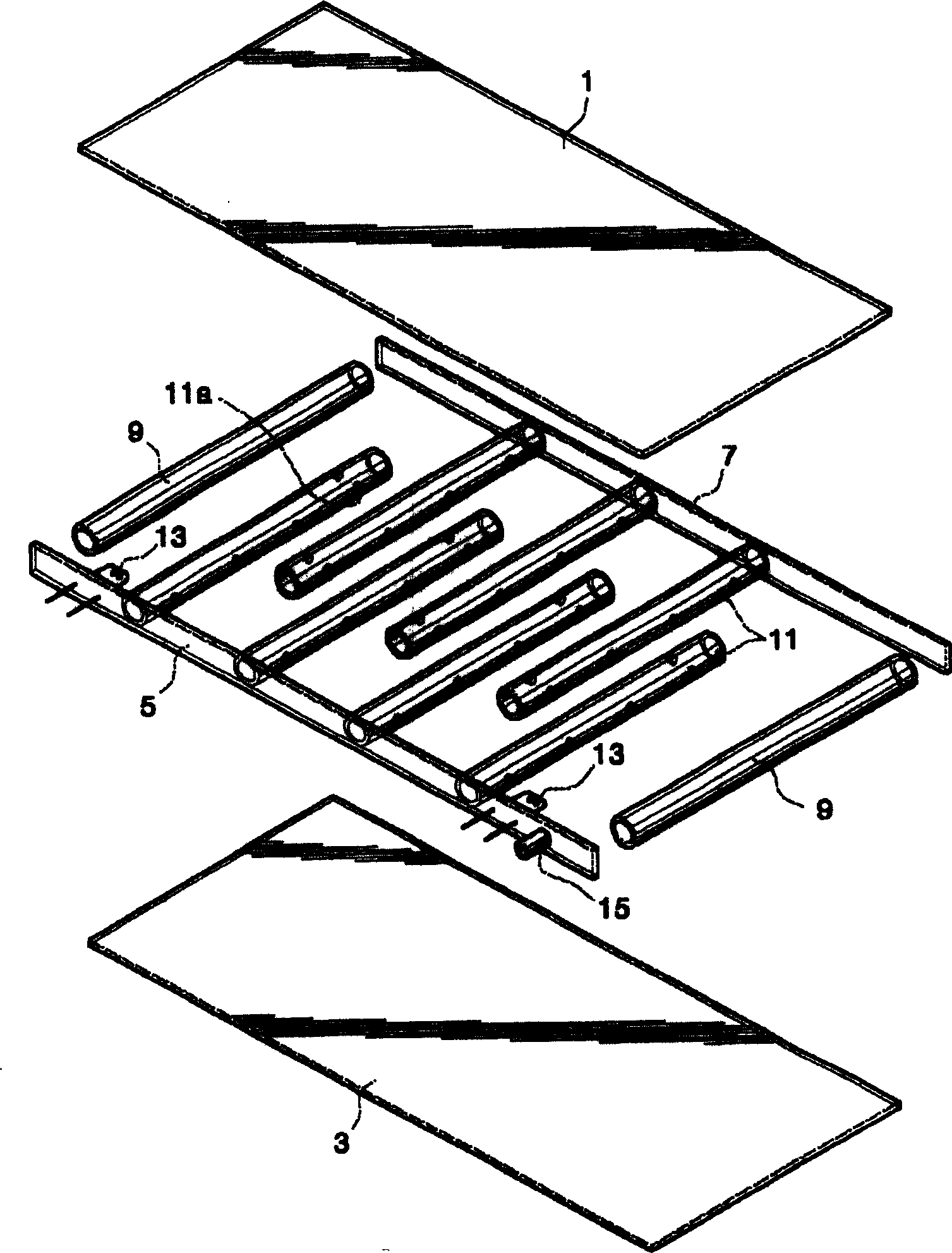
[0039] figure 1 and 2 A flat-type fluorescent lamp according to a first embodiment of the present invention is shown. As shown in the figure, the flat fluorescent lamp of the present invention is defined by a rectangular parallelepiped outer lamp body and a light emitting device for realizing a surface light source such as a backlight of a flat panel display.

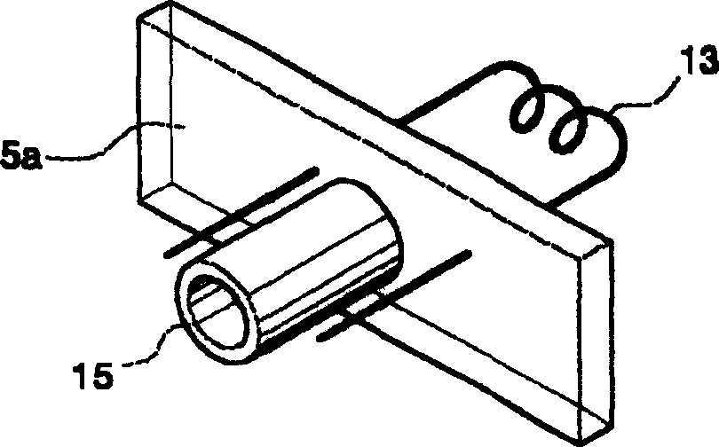
[0040] The outer lamp body includes a front panel 1 and a rear panel 3 , and longitudinal and transverse seals 5 , 7 and 9 for sealing the space defined between the front panel 1 and the rear panel 3 . Here, the back plate 3 and the seals 5, 7 and 9 are made of a transparent or translucent material. Also, a reflective layer is formed on the rear plate 3 .

[0041] In addition, the transverse seal 9 may be formed by a tubular spacer. The length of each tubular spacer 9 is the same as the width of the outer lamp body. The longitudinal seals 5 and 7 are formed by side panels.

[0042] As a characteristic of the inven...

Embodiment 2

[0062] Figure 6 and 7 A flat-type fluorescent lamp according to a second embodiment of the present invention is shown.

[0063] As shown in the figure, the flat fluorescent lamp of the invention described in this embodiment includes the outer lamp body as in the first embodiment.

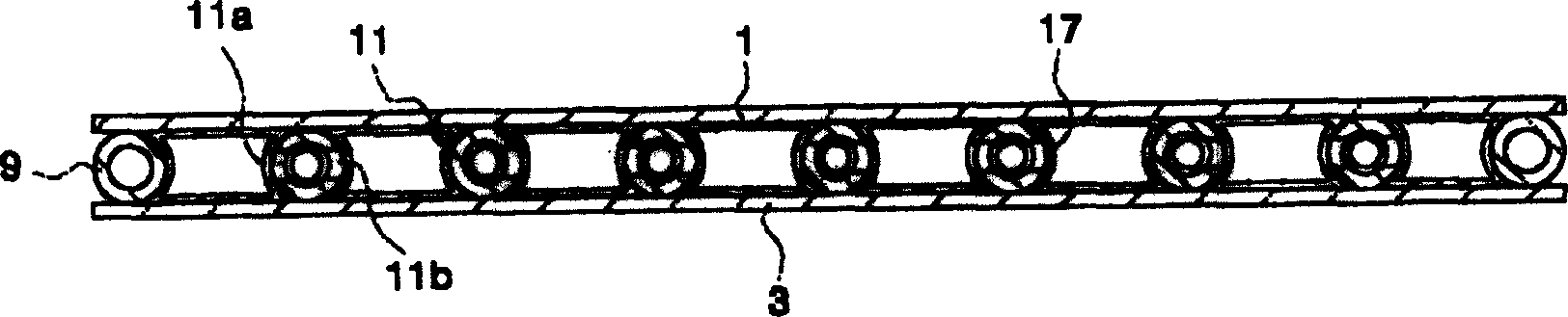
[0064] As a feature of this embodiment, a plurality of tubular spacers 111 are provided between the front panel 1 and the rear panel 3 .

[0065] Each tubular spacer 111 is designed to be shorter than the width of the outer lamp body. That is, the length of the tubular spacer 111 is 1 / 10 to 1 / 2 of the width of the outer lamp body. The tubular spacers 111 can be arranged randomly or aligned in a row. Like the first embodiment, the section of the tubular spacer 111 can be designed in various shapes, such as circular, elliptical or polygonal.

[0066] The above structure and arrangement of the tubular spacer 111 according to the present invention can make it easier to deposit the phosphor layer 1...

Embodiment 3

[0070] The third embodiment is the same as the first and second embodiments except that the phosphor layer 17 is further optimized to improve luminous efficiency and luminous brightness.

[0071] That is, in the third embodiment, the thickness "d" of the phosphor layer 17 deposited on the inner surface of the outer lamp is limited to satisfy the following range:

[0072] d=4log e W~d=4log e W+16

[0073] Among them, W represents the electric power of the lamp.

[0074] Utilize the test result that above-mentioned condition obtains as table 1 and Figure 9 shown. In this experiment, a three-wavelength phosphor was used as the fluorescent material, and for the colors of red R, green G and blue B of the fluorescent material, Y 2 o 3 :Eu, LaPO 4 : Ce, Tb and (Sr, Ca, Ba) 10 (PO 4 ) 6 C 12 :Eu. In addition, the phosphor has an average particle size in the range of 2-10 μm, and is distributed in an area of ​​80±10% of the entire surface area.

[0075] Alternatively, pho...


PUM


Abstract

The present invention discloses a flat type fluorescent lamp that is improved in its light emission efficiency and brightness by installing a tube spacer between 2 panels. A flat type fluorescent lamp includes an outer lamp body comprising front and rear panels, and circumference seal members, and tube spacers installed in the outer lamp body to divide the discharge spaces in plural sections communicating with each other to define a discharge path, a phosphor layer deposited on the outer lamp body and the tube spacers, and a discharge electrode supported on the outer lamp body.

Description

technical field [0001] The present invention relates to a flat fluorescent lamp, more specifically, to a fluorescent lamp which eliminates the non-luminous area and expands the luminous area by installing a tubular spacer in the outer lamp body, thereby improving its luminous efficiency and brightness, and then realizes an inventive Surface light source. Background technique [0002] Flat-panel fluorescent lamps are widely used as backlights for flat-panel display screens, and can also be used as light-emitting devices, and their application fields have been significantly expanded. [0003] A conventional flat fluorescent lamp consists of two glass bases and side panels, which are assembled to each other. Spacers are disposed between the glass substrates to maintain a constant interval between the substrates while also providing a discharge path. Phosphors are deposited on the inner surface of the outer lamp body, and discharge electrodes are installed at both ends of the ...

Claims


Application Information

Patent Timeline
Patent Type & Authority Applications(China)
IPC IPC(8): H01J61/06H01J17/16H01J61/04H01J61/067H01J61/30H01J61/42
CPCH01J61/305
Inventor 李桂承
Owner 李桂承
Why Eureka
Try Eureka