Carriage control device of instrument lathe

A technology for instrument lathes and control devices, which is applied in the field of instrument lathes and devices for controlling instrument lathes. It can solve the problems of too fast movement of the carriage, which affects the processing precision and workpiece processing quality, achieves high processing efficiency, improves processing accuracy and processing The effect of speed and simple structure

Inactive Publication Date: 2005-08-10
王永德
View PDF1 Cites 5 Cited by
  • Summary
  • Abstract
  • Description
  • Claims
  • Application Information

AI Technical Summary

Problems solved by technology

However, the disadvantage of this structure is that the carriage completely uses the cylinder to control its movement, which causes the carriage to move too fast, which directly affects the machining accuracy and the processing quality of the workpiece.

Method used


Image

  • Carriage control device of instrument lathe
  • Carriage control device of instrument lathe
  • Carriage control device of instrument lathe

Examples


Embodiment Construction

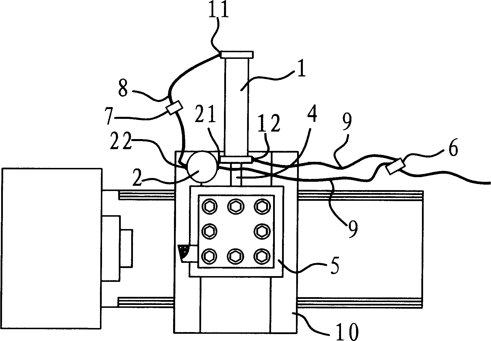
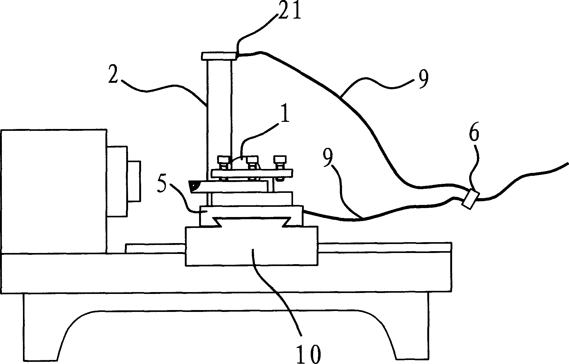
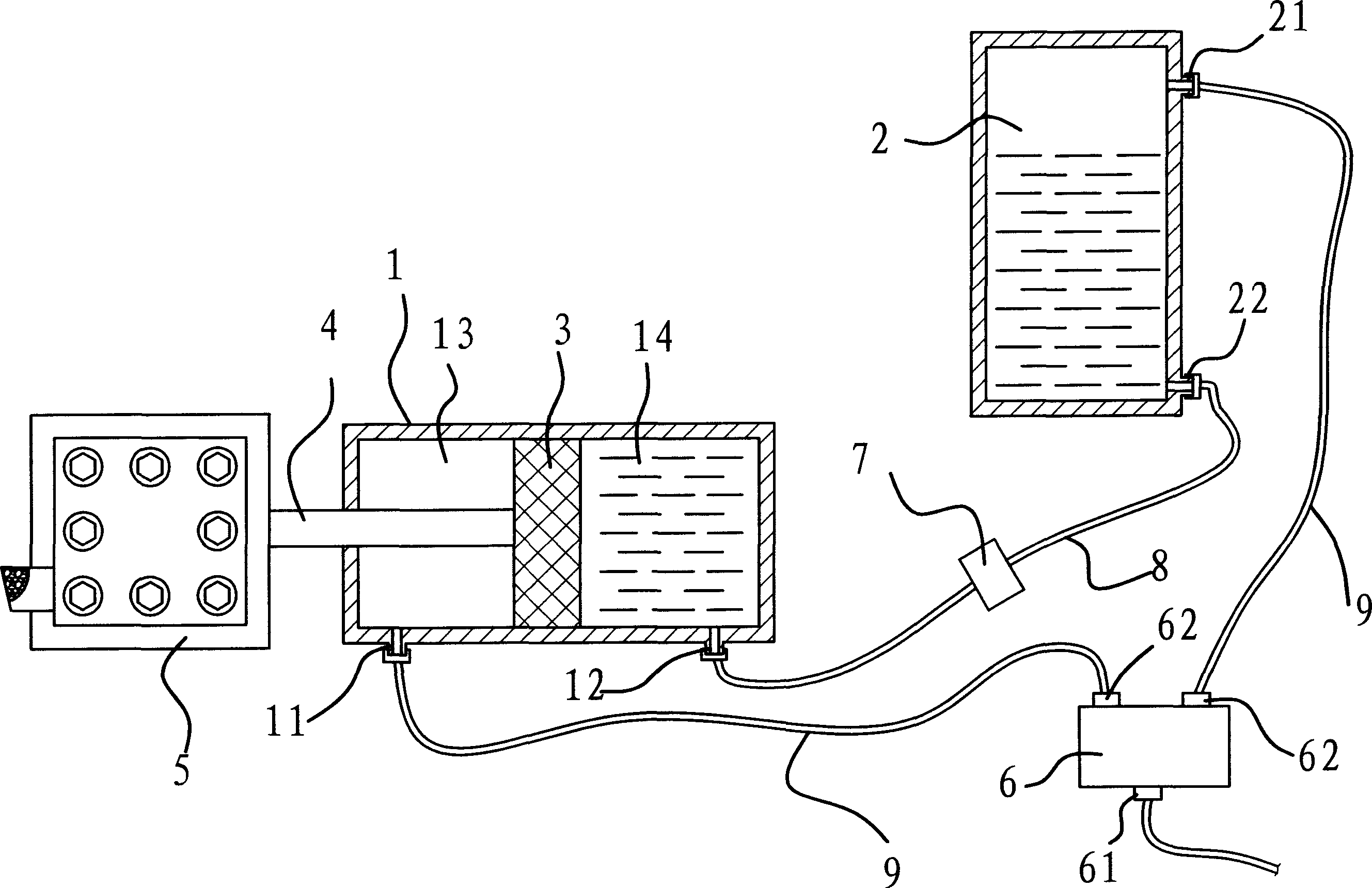
[0016] like figure 1 and figure 2 As shown, the carriage control device of the instrument lathe is set on the bed body of the lathe, which includes a first cylinder 1, a second cylinder 2, a piston 3, a piston rod 4, a throttle valve 6, an oil pipe 8 and an air pipe 9 and other parts. In this embodiment, the outer end of the piston rod 4 is fixedly connected with the small carriage 5 of the instrument lathe. The first cylinder body 1 and the second cylinder body 2 are fixed on the large carriage 10 of the instrument lathe.

[0017] like figure 1 and figure 2 As shown, the first cylinder body 1 is placed horizontally, and a piston 3 that can slide back and forth is arranged in its inner chamber. The piston 3 divides the inner cavity of the first cylinder 1 into a front cavity 13 and a rear cavity 14 . The inner end of the piston rod 4 is fixedly connected with the piston 3, and the outer end stretches out from the first cylinder 1, and is fixedly connected with the smal...


PUM


Abstract

A control mechanism for the tool carriage of instrument lathe is composed of the first cylinder with piston and piston rod fixed to said tool carriage, the second cylinder, a speed regulating valve with an air inlet connected to air pump and two air outlets connected respectively to the upper connection tubes of both cylinders, and an oil tube connected between two lower connection tubes of both cylinders. Its advantages aresmooth advancing and high withdrawing speed.

Description

technical field [0001] The invention belongs to the technical field of machinery, and relates to an instrument lathe, in particular to a device for controlling the instrument lathe. Background technique [0002] At present, in the existing instrument lathes, the carriage is usually controlled by a handle to advance and retreat. Since this structure is manually operated, it is time-consuming and laborious, and the work efficiency is low. In order to overcome the above shortcomings, some instrument lathes use cylinders to control the movement of their carriages. As provided by Chinese patent 02261082.0, "instrument lathe pallet air control automatic device" mainly is to set a cylinder on the pallet, and the push-pull rod connected with the piston in the cylinder stretches out the cylinder. Control the moving distance of the carriage by adjusting the length of the push-pull rod. In this way, the operation of the instrument lathe is convenient, and semi-automatic is realized,...

Claims


Application Information

Patent Timeline
Patent Type & Authority Applications(China)
IPC IPC(8): B23Q5/34F15B15/14
Inventor 王永德
Owner 王永德
Why Eureka
Try Eureka