Calibrated catalyst carrier body with corrugated casing and method for manufacturing the same

A shell and matrix technology, applied in the field of catalyst matrix and its manufacturing, can solve the problems of component failure and unevenness, and achieve the effect of improving stability

Inactive Publication Date: 2005-08-10
EMITEC EMISSIONSTECHNIK
View PDF4 Cites 9 Cited by
  • Summary
  • Abstract
  • Description
  • Claims
  • Application Information

AI Technical Summary

Problems solved by technology

This results in an inhomogeneous structure which

Method used


Image

  • Calibrated catalyst carrier body with corrugated casing and method for manufacturing the same
  • Calibrated catalyst carrier body with corrugated casing and method for manufacturing the same
  • Calibrated catalyst carrier body with corrugated casing and method for manufacturing the same

Examples


Embodiment Construction

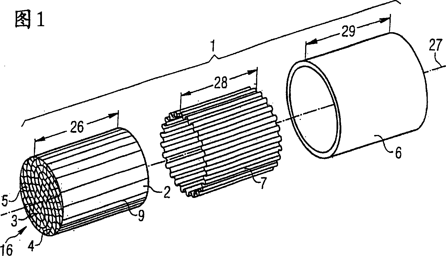
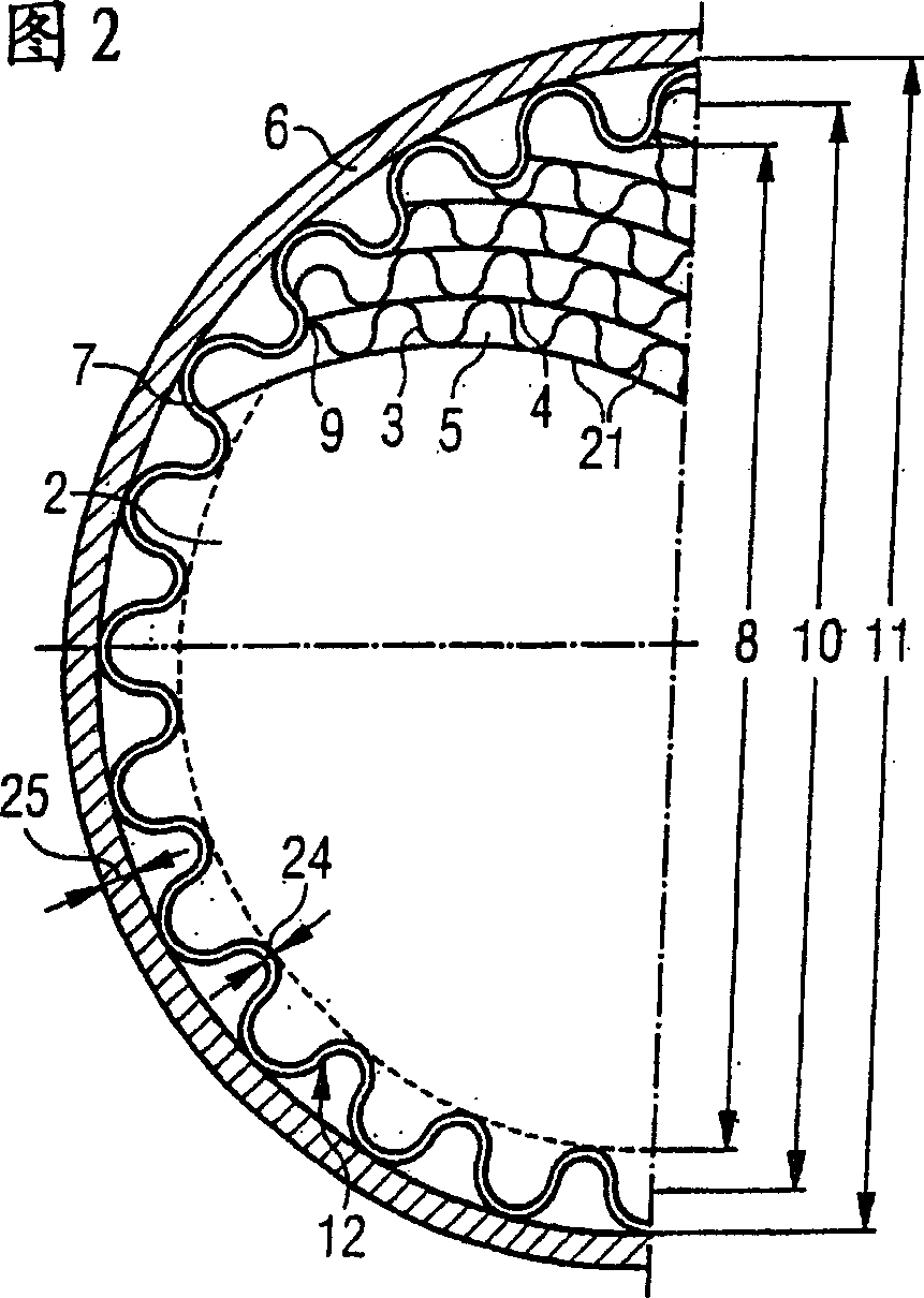
[0065] 1 shows an exploded perspective view of an embodiment of a catalytic converter base body 1 according to the invention, which comprises a honeycomb body 2 and a corrugated shell 7 arranged centrally with respect to the honeycomb body 2 or an axis 27. and a housing 6 which is also arranged centrally. Here the honeycomb body 2 is of cylindrical design, wherein the honeycomb body comprises a plurality of corrugated layers 3 and smooth layers 4 which are arranged or stacked and / or wound in such a way that their ends 9 at least partially form the design The outer periphery of the cylindrical honeycomb body 2. Due to the alternating arrangement of corrugated layers 3 and smooth layers 4 , channels 5 are formed through which exhaust gas can flow. In the illustrated embodiment of the honeycomb body 2 , the channels 5 extend from one end side 16 to the opposite end side 16 over the entire length 26 of the honeycomb body 2 , wherein the channels are designed substantially paralle...


PUM


Abstract

Disclosed is a method for producing a catalyst carrier element (1) comprising a honeycomb body (2) which is provided with a plurality of at least partly structured layers (3, 4) forming channels (5) that are penetrated by a fluid, a housing (6) which at least partly envelops the honeycomb body (2), and at least one corrugated sheath (7) which is arranged between the honeycomb body (2) and the housing (6) and connects the honeycomb body (2) to the housing (6). The inventive method comprises the following steps: - the honeycomb body (2) is produced, said honeycomb body (2) having an outer dimension (8) that is formed at least in part by ends (9) of the layers (3, 4); the at least one corrugated sheath (7) having a profile (10) is produced; - a housing (6) having an inner contour (11) is produced; - the honeycomb body (2) is inserted into the at least one corrugated sheath (7); - the at least one corrugated sheath (7) comprising the honeycomb body (2) is inserted into the housing (6); - the housing is calibrated (6), at least the inner contour (11) and preferably also the profile (10) of the at least one corrugated sheath (7) being reduced while the ends (9) snap into the structure of the corrugated sheath (7) and almost entirely rest against said corrugated sheath (7). At least 90 percent of the ends (9) of the catalyst carrier element which is produced according to the inventive method are connected to the at least one corrugated sheath (7) by means of a joining technique.

Description

technical field [0001] The invention relates to a catalytic converter base body according to the preamble of claim 18 and a method for its production. The catalytic converter substrate is particularly suitable for reducing harmful substance components of the exhaust gas of a motor vehicle internal combustion engine. Background technique [0002] Catalyst substrates are used in the exhaust systems of internal combustion engines of vehicles, such as diesel or gasoline engines. For this purpose, the catalyst substrate is usually provided with a support layer (in particular a washcoat) which is characterized by a large surface area and is usually impregnated with at least one catalytically active material (eg platinum, rhodium, etc.). When the exhaust gas comes into contact with the catalytically active material, the reduction of harmful substances contained in the exhaust gas, such as carbon monoxide, unsaturated hydrocarbons, nitrogen monoxide, takes place. In order to be ab...

Claims


Application Information

Patent Timeline
IPC IPC(8): B01D53/86B01J32/00B01J33/00B01J35/04F01N3/28
CPCF01N2450/22F01N2450/20F01N2330/02F01N3/2875F01N3/281B01J35/04F01N2330/04Y02A50/20F01N3/28
Inventor F·库尔斯U·施密特
Owner EMITEC EMISSIONSTECHNIK
Why Eureka
Try Eureka