Mobile magnetic levitation system

A mobile device and magnetic levitation technology, which is applied in the direction of display devices, magnetic attraction or thrust holding devices, instruments, etc., can solve the problems of floating bodies that cannot move, expand expressiveness and application fields, enhance visual effects, and expand application range Effect

Inactive Publication Date: 2005-08-17
NINGBO TIANMING ELECTRONICS
View PDF2 Cites 10 Cited by
  • Summary
  • Abstract
  • Description
  • Claims
  • Application Information

AI Technical Summary

Problems solved by technology

[0004] In order to overcome the deficiency that the floating body cannot move in the prior art,

Method used


Image

  • Mobile magnetic levitation system
  • Mobile magnetic levitation system
  • Mobile magnetic levitation system

Examples


Embodiment 1

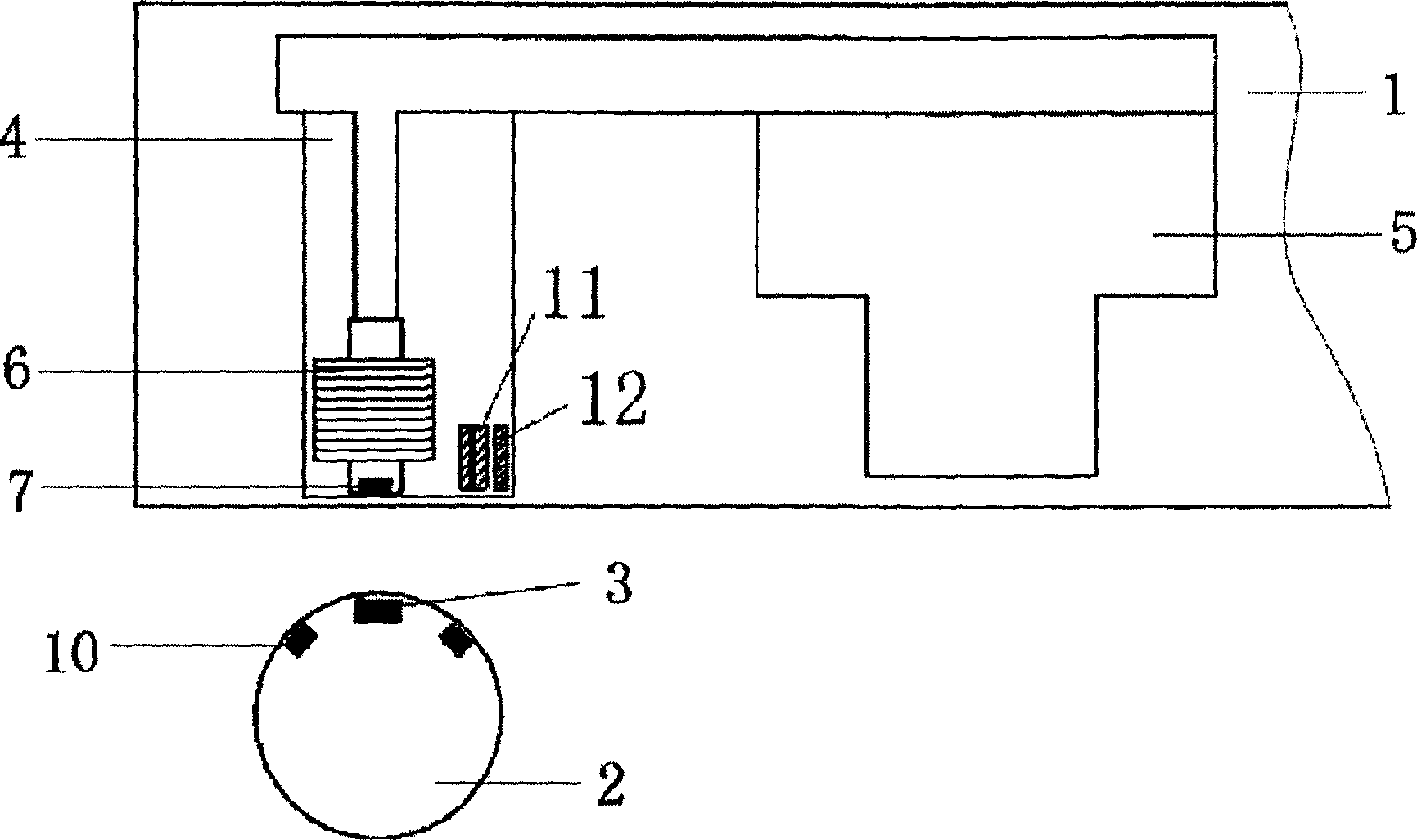
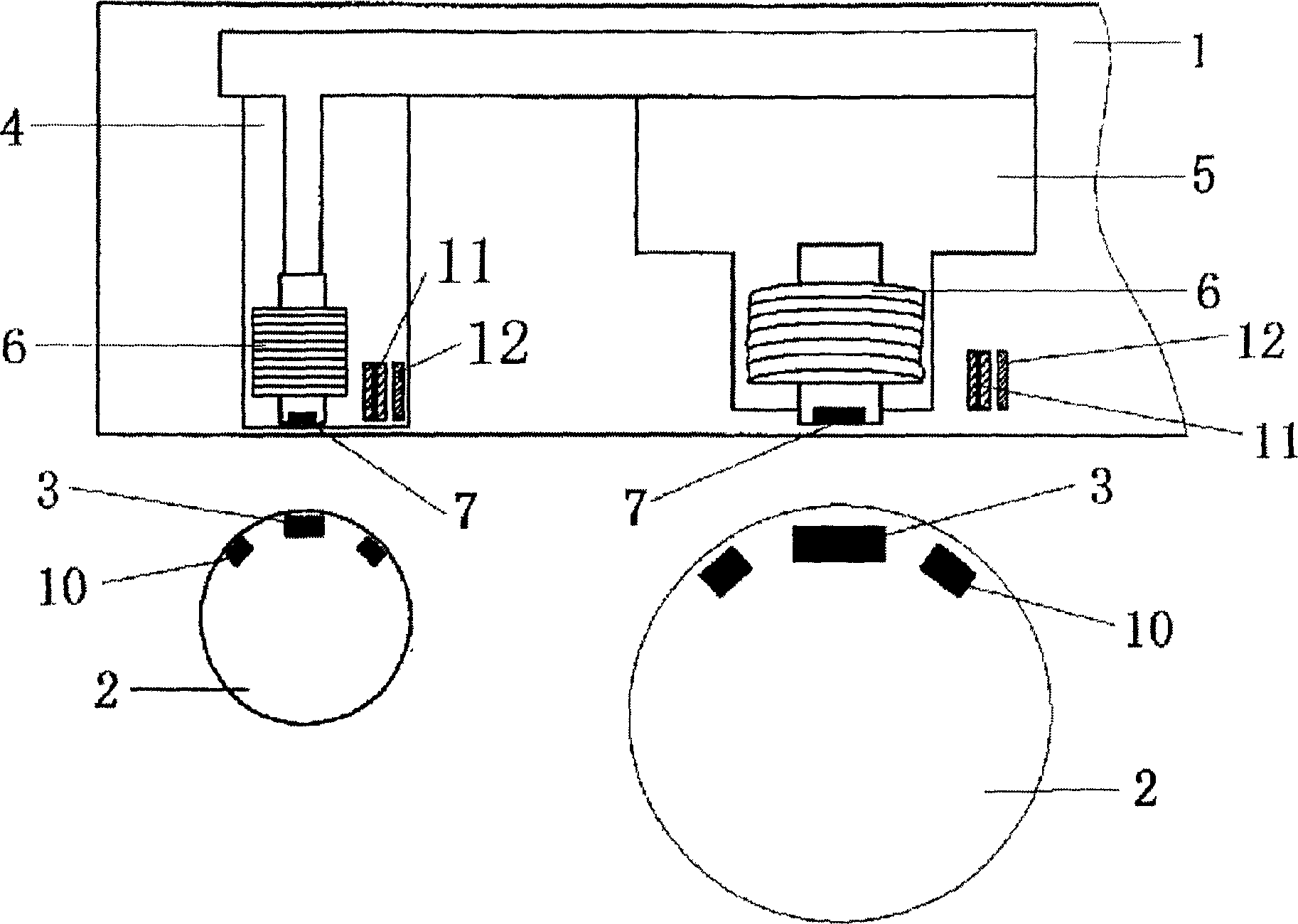
[0020] refer to figure 1 , The mobile magnetic levitation device includes a frame box 1, a floating body 2 is arranged below the frame box, and a permanent magnet 3 is installed on the center of gravity of the floating body 2. The floating body 2 can be a celestial body model, an airplane and various handicrafts.

[0021] A moving device consisting of a turntable 4 , a motor 5 and a mechanical transmission mechanism is installed on the frame box 1 , the motor 5 is connected to the mechanical transmission mechanism, and the mechanical transmission mechanism is connected to the turntable 4 . The electromagnet 6 corresponding to the position of the permanent magnet 3 in the floating body 2 is installed on the said turntable 4, and a displacement sensor 7 and a magnetic levitation control circuit for measuring the position of the floating body 2, and the displacement sensor 7 can be selected from a linear Hall Commonly used sensors such as Er element, magnetosensitive element, dis...

Embodiment 2

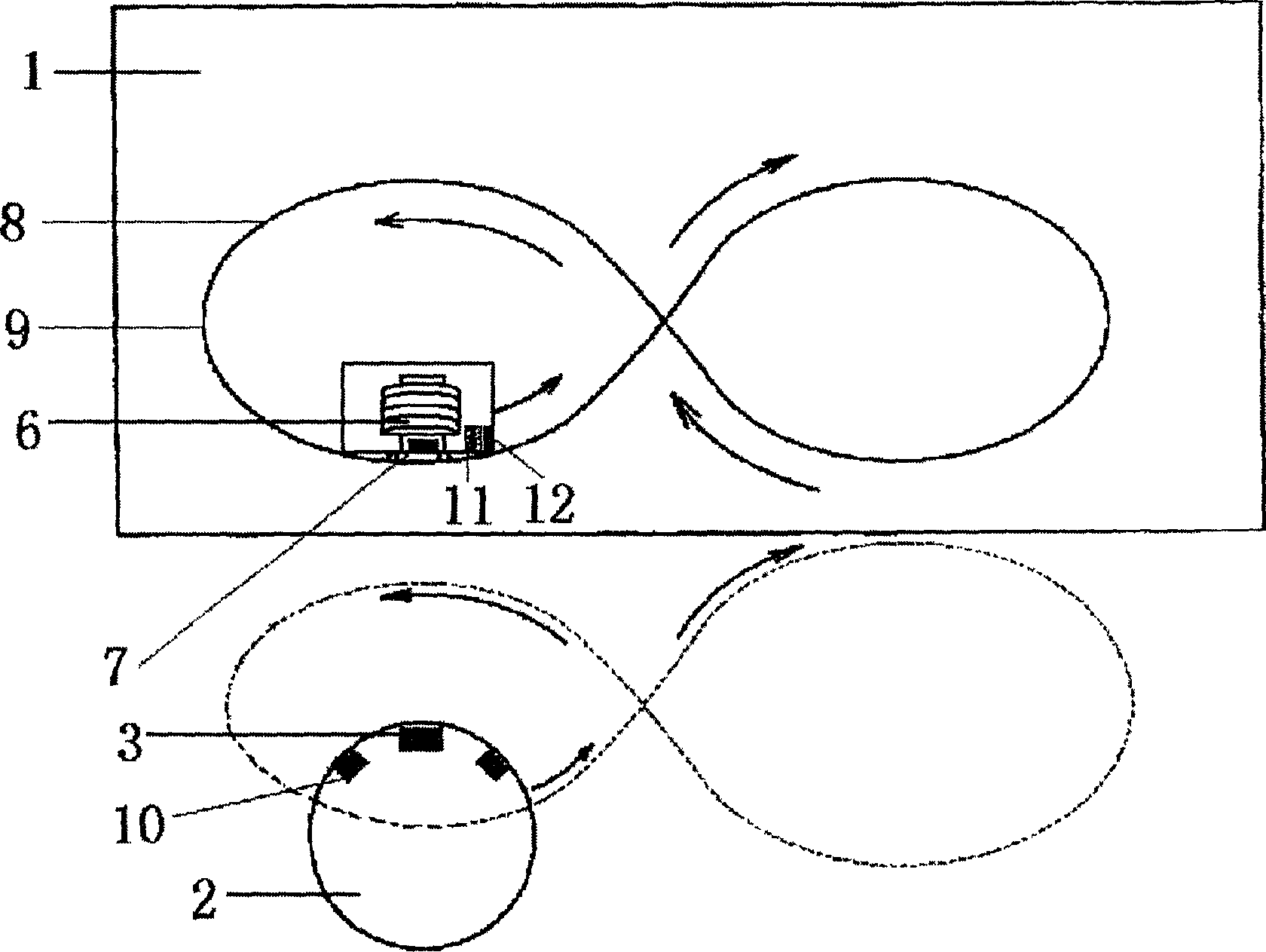
[0025] refer to figure 2 1, a guide rail 8 is installed on the frame box body 1, the electric wheel of a car model 9 cooperates with the guide rail 8, and the electromagnet 6 and the displacement sensor 7 are installed in the described car model 9. Because the electromagnet 6 and the displacement sensor 7 are arranged in the car model 9, when the car model 9 moves, the electromagnet 6 and the displacement sensor 7 move together with the car model 9, and the floating body 2 attracted by the electromagnetic attraction force of the electromagnet 6 also rotates together with the car model 9 , so as to generate a running track corresponding to the guide rail 8, such as figure 2 Shown by the dotted line. The remaining implementation modes are the same as the first embodiment.

Embodiment 3

[0027] A manipulator is installed on the frame box, and a carrier is installed on the manipulator, and the electromagnet and the displacement sensor are installed in the carrier. Since the electromagnet and the displacement sensor are arranged in the carrier, when the manipulator drives the carrier to move, the electromagnet and the displacement sensor move together with the carrier, and the floating body attracted by the electromagnetic attraction of the electromagnet also rotates with the carrier, thereby generating a The motion trajectory of the manipulator corresponds to the running trajectory. The remaining implementation modes are the same as the first embodiment.


PUM


Abstract

This invention relates to movable magnetic suspension device, which comprises rack part, floater below the rack box with permanent magnetism, wherein the said magnetism is located on the gravity line of the said floater; the said rack box contains electromagnetism to balance floater dropping gravity interacting with the said permanent magnetism and displacement sensor to measure the floater position and magnetism suspension control circuit. The movable device is located with rotation generation device to make the floater rotate cooperating with the rotation magnetism to realize the floater self-rotation.

Description

(1) Technical field [0001] The invention relates to a magnetic levitation device. (2) Background technology [0002] Teaching supplies, handicrafts, souvenirs, models and many other products are made into magnetic levitation devices with good visual effects. In the past various patents and products related to magnetic levitation devices, the floating body can be magnetically suspended or can automatically rotate while magnetically levitating, but the floating body cannot move. [0003] The Chinese patent No. 92215714.6 provides a magnetic levitation globe, but its floating body of the magnetic levitation globe cannot rotate, and the floating body cannot move. The Chinese patent No. 00115354.4 provides a magnetic levitation device, the floating body of the magnetic levitation device can rotate, but the floating body still cannot move. Because the floating body cannot move, the visual effect is limited, and the application range is also limited. (3) Contents of the inventi...

Claims


Application Information

Patent Timeline
IPC IPC(8): G09F19/02H02N15/00
Inventor 唐建一俞益庭张旭辉
Owner NINGBO TIANMING ELECTRONICS
Why Eureka
Try Eureka