Insulation monitoring method for low current neutral grounding systems and apparatus for realizing the method

A small current grounding and current technology, applied in the direction of measuring devices, measuring electricity, measuring electrical variables, etc., can solve problems such as resonance

Inactive Publication Date: 2005-09-07
中国石化集团河南石油勘探局水电厂
View PDF0 Cites 11 Cited by
  • Summary
  • Abstract
  • Description
  • Claims
  • Application Information

AI Technical Summary

Problems solved by technology

[0004] The purpose of the present invention is to address the deficiencies in the prior art, and to provide a low-current grounding system based on the problem that electromagnetic voltage tran...

Method used


Image

  • Insulation monitoring method for low current neutral grounding systems and apparatus for realizing the method
  • Insulation monitoring method for low current neutral grounding systems and apparatus for realizing the method
  • Insulation monitoring method for low current neutral grounding systems and apparatus for realizing the method

Examples


Embodiment 1

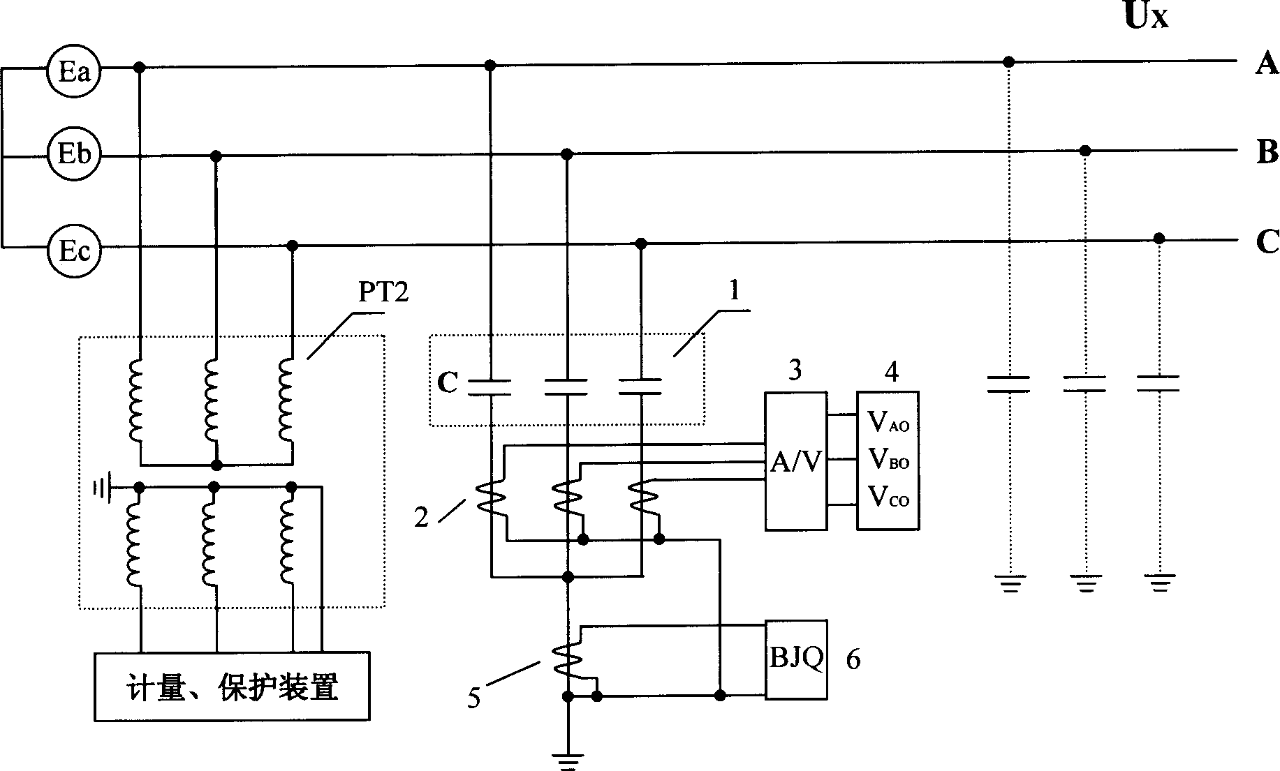
[0023] Embodiment 1: with reference to attached figure 2 , each phase of the non-inductive element group 1 is composed of a single capacitor C or resistor R. figure 2 The middle one is a system voltage measurement system composed of a single capacitor C with the method of measuring current, combined with a voltage transformer PT2 whose primary winding is star-connected. Since the measurement principle and method of the voltage transformer PT2 is a well-known technology in the field of electrical measurement, it will not be described here, and only the application of the non-inductive element group 1 will be described below.

[0024] It is known that the capacitance of the capacitor is C, and its capacitive reactance Xc=1 / ωC; when the system is normal, the three-phase ground voltage is the system line voltage Ux times, the current flowing through the capacitor is I CA = I CB = ...

Embodiment 2

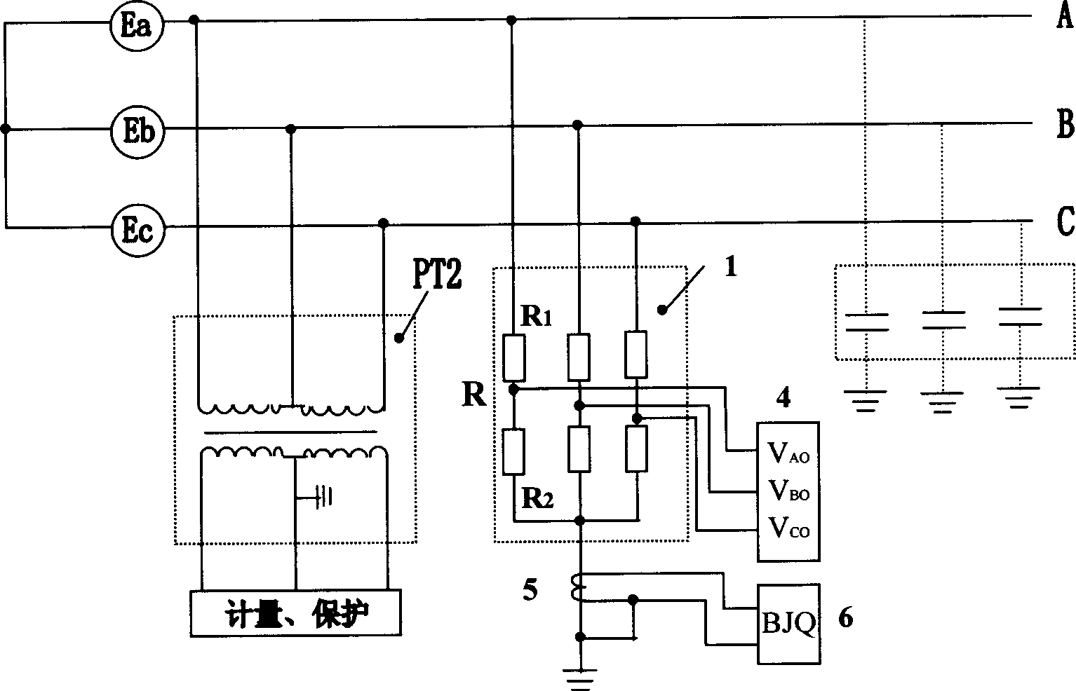
[0026] Embodiment 2: with reference to attached image 3 , each phase of the non-inductive element group 1 is composed of two or more resistors R or capacitors C connected in series. image 3 In the middle, two resistors R are connected in series, and the method of measuring the voltage of the voltage dividing element is used to form a voltage measurement system together with the voltage transformer PT2 whose primary winding is an incomplete triangle (V-V connection). image 3 It can be seen that the resistance value (or capacitive reactance) of each phase is the sum of the resistance values ​​of each component, that is, R A = R B = R C = R 1 +R 2 , when the system is normal, the current of each phase is I A = I B = I C = U x / ( 3 × ...

Embodiment 3

[0027] Embodiment 3: with reference to attached Figure 4 , each phase of the non-inductive element group 1 is composed of one or several capacitors C and resistors R connected in series. Figure 4 In the middle, a capacitor C and a resistor R are connected in series to measure the phase current, and together with the voltage transformer PT2 whose primary winding is delta-connected, the system voltage measurement system is formed. In this example, the impedance of each phase is divided by Z A = Z B = Z C =(R 2 +X C 2 ) 1 / 2 With embodiment 1 (see appendix figure 2 ) in X C Except that =1 / ωC is different, all the other are identical with embodiment 1. In this example, the method of obtaining the relative ground voltage by means of voltage division can also be used, only the voltage division ratio at this time should be K=(R 2 +X C 2 ) 1 / 2 / R, all the other are identical with embodiment 2.

[0028] It can be seen that when the non-inductive element group 1 contains mo...


PUM


Abstract

The invention relates to a method and system of insulating monitoring the low current neutral grounding system, including the non-inductance cluster 1 which accesses system in star patching and the neutral point grounding directly. The method comprises the following steps: (a) measuring the current or voltage parameter of the cluster1 by the measuring device2, providing the current or voltage information of the system relative to the ground; (b) transferring the current to the voltage through the current-to-voltage converter;(c) displaying the three-phase voltage of the system by the voltage display4 and monitoring the insulation of the system;(d) applying the neutral conductor of alarming device5 connected to the cluster1 to measure the residual current of cluster1; (e) displaying the insulation condition by the alarm 6 and monitoring the low current neutral grounding system. Said invention can avoid the basic frequency, double frequency and frequency division resonance of the voltage transformer.

Description

1. Technical field [0001] The invention relates to an insulation monitoring method for a small current grounding system and a device for realizing the method, belonging to the field of electric power technology, in particular to an insulation monitoring technology for a small current grounding system and a technology for eliminating ferromagnetic resonance overvoltage of an electromagnetic voltage transformer . 2. Background technology [0002] In the small current grounding system, the primary winding connected to the busbar of the power plant and substation is usually star-connected and the neutral point is directly grounded. The electromagnetic voltage transformer provides system relative grounding for insulation monitoring devices, metering and protection devices. Voltage, zero sequence voltage, line voltage, phase voltage information. It can be seen from Figure 1 that the ground parameters of the system at this time are in addition to the capacitance C of the power gen...

Claims


Application Information

Patent Timeline
IPC IPC(8): G01R31/02
Inventor 刘振伶刘彦生姜俊莉刘占荣程志明
Owner 中国石化集团河南石油勘探局水电厂
Why Eureka
Try Eureka