
Digital lamp controlled switch with remote controller

A digital and light control technology, applied in electronic switches, light circuit layout, lighting devices, etc., can solve the problems of no display function, no reports, etc., and achieve the effect of improving the grade.

Inactive Publication Date: 2005-09-07
DONGGUAN PERFECT SCI & TECH +1
View PDF5 Cites 5 Cited by
  • Summary
  • Abstract
  • Description
  • Claims
  • Application Information

AI Technical Summary

Problems solved by technology

[0003] Retrieval of relevant materials including Chinese patents shows that at present, Chinese patents 91107351.5; 96118132.X; 99115766.4; 00803985.2; The structure of intelligent digital control and switch structure with display function has not been reported yet.

Method used


Image

  • Digital lamp controlled switch with remote controller
  • Digital lamp controlled switch with remote controller
  • Digital lamp controlled switch with remote controller

Examples


Embodiment 1

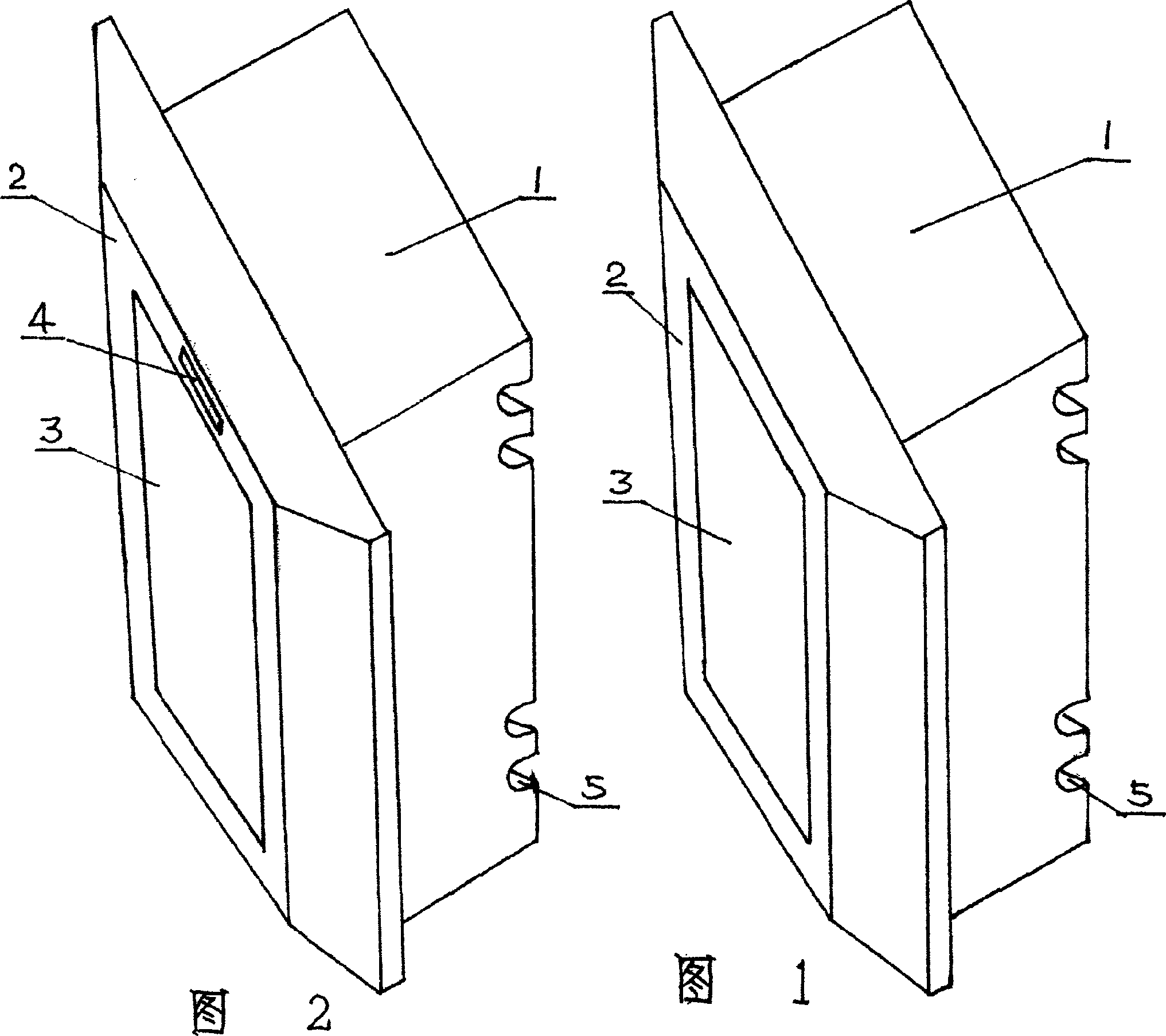
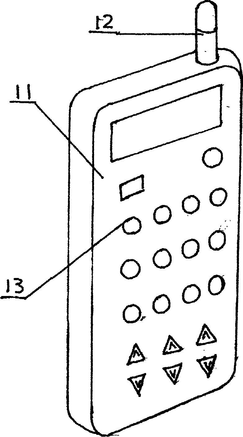
[0014] See Figure 1 and image 3 , this embodiment is the switch main body of the aluminum alloy mask, the main body of the switch has a housing 1, the front end of the housing 1 is fixedly installed with an aluminum alloy mask 2 with a plastic skeleton inside, and the touch and display are fixed in the middle of the mask 2. Combination board 3; the heart of housing 1 is equipped with the circuit of known touch and display combination board 3 and the relevant microprocessor circuit of the present invention; the antenna lead in the circuit can be connected with aluminum alloy face shield 2 through any point; housing The rear end of 1 is provided with the power cord head hole 5 of power connector and power output connector. The remote control part is composed of a main housing 11, the upper end of the main housing 11 is provided with a remote control antenna 12, and various remote control switch buttons 13 are arranged on the surface of the main housing 11; In this embodiment, t...

Embodiment 2

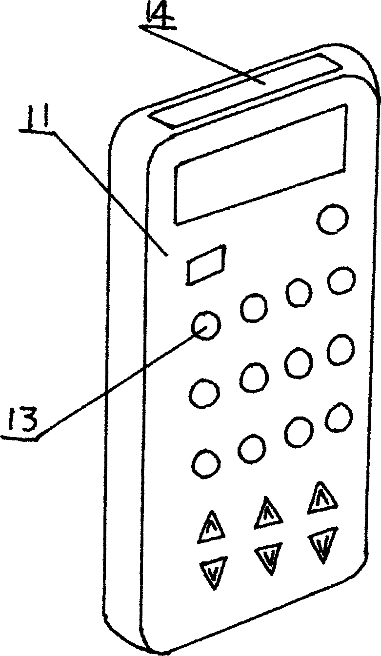
[0016] See Figure 2 and image 3 , the present embodiment is the switch main body of the plastic mask, the switch main body part has a housing 1, the front end of the housing 1 is fixedly mounted with a plastic mask 2, the upper end of the mask 2 is provided with an infrared receiving window 4, and the middle of the mask 2 is fixed with a touch and display switch. An integrated combination board 3; the circuit of the known touch and display combination board 3 and the related microprocessor circuit of the present invention are installed in the heart of the housing 1; the rear end of the housing 1 is provided with a power terminal and a power output connector Power cord hole 5. The remote control part consists of a main housing 11, the upper surface of the main housing 11 is provided with an infrared emission window 14, and the surface of the main housing 11 is arranged with various remote control switch buttons 13; the main housing 11 is equipped with a micro-processing circuit...


PUM


Abstract

The invention discloses a novel digital light control switch, a switch among the articles for daily use, composed of a main body and a remote controller, there is a shell in the main body, there are metallic and plastic masks fixed at the front end of the shell, and there is a touch-display combined plate fixed in the middle of the masks; the inner center of the shell is installed with a circuit of the combined plate and a related microprocessor circuit; the back end of the shell is made with power supply wiring points and power supply output connectors. And the remote controller is composed of a main shell, where the main shell is provided with remote control antenna or infrared ray window, the right surface of the main shell is provided with various remote control switching keys; the microprocessor circuit is installed inside the main shell. The main body and remote controller of the invention can be used, combinedly and the main body can also be used, singly. Here, as soon as switching on the power supply, the display will display the related working state menus and to touch the relative display of the switch by hand is to implement the on, off, dimming, delayed off, etc, for all the lights.

Description

technical field [0001] The invention relates to an electric light switch used in people's daily life and workplaces, in particular to a novel digital light control switch with a remote controller. Background technique [0002] The purpose of ordinary switches is to control the on and off of electric lights. However, the existing mechanical products are relatively primitive and have been made consistently for decades. Some are made of wood, and some are made of bakelite. Now the most common A plastic switch is used. So far, the actual structure of the switch has not changed much, but the appearance has changed more and more beautiful and generous, and some switch panels can gather three to four switches together and so on. With the development of electronic technology, many electronic industries are advancing by leaps and bounds, but the research and development of switch structure and intelligence lags behind. [0003] Retrieval of relevant materials including Chinese pate...

Claims


Application Information

Patent Timeline
IPC IPC(8): H03K17/96H05B37/02
Inventor 陈鸿贤苏腾刘鲁江游建辉
Owner DONGGUAN PERFECT SCI & TECH
Features
  • Generate Ideas
  • Intellectual Property
  • Life Sciences
  • Materials
  • Tech Scout
  • Unparalleled Data Quality
  • Higher Quality Content
  • 60% Fewer Hallucinations
Learn More